795–08691 GM 12–07 ® www.graymills.com Air Operated Double Diaphragm Pumps Operations and Maintenance Instructions WARNING/CAUTIONS Read all these SAFETY INSTRUCTIONS BEFORE installing or using this equipment. Keep this manual handy for reference/training. DACT50 Acetal NPT Pumps* PLHG50 Polypropylene Pumps PQHG50 PLTG50 PQTG50 * These models are certified. Graymills Corporation 3705 N. Lincoln Avenue Chicago, Illinois 60613 773-248-6825 FAX 773-477-8673 www.graymills.
Table of Contents Symbols Safety Warnings . . . . . . . . . . . . . . . . . . . . . . . . . . . . . . . . . 2 Technical Data . . . . . . . . . . . . . . . . . . . . . . . . . . . . . . . . . . 4 Installation . . . . . . . . . . . . . . . . . . . . . . . . . . . . . . . . . . . . . 5 Operation . . . . . . . . . . . . . . . . . . . . . . . . . . . . . . . . . . . . . 10 Maintenance . . . . . . . . . . . . . . . . . . . . . . . . . . . . . . . . . . . 11 Troubleshooting . . . . . . . . . . . . . . . . . . .
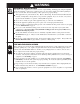
WARNING EQUIPMENT MISUSE HAZARD Any misuse of the equipment or accessories, such as overpressurizing, modifying parts, using incompatible chemicals and fluids, or using worn or damaged parts, can cause them to rupture and result in splashing in the eyes or on the skin, other serious injury, or fire, explosion or property damage. This equipment is for professional use only. Observe all warnings. Read and understand all instruction manuals, warning labels, and tags before you operate this equipment.
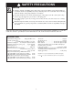
SAFETY PRECAUTIONS CAUTION Verify the chemical compatibility of the pump wetted parts and the substance being pumped, flushed or recirculated. Chemical compatibility may change with temperature and concentration of the chemical(s) within the substance being pumped, flushed or recirculated. The pump should not be used for the structural support of the piping system. Be certain system components are properly supported to prevent stress on the pump parts.
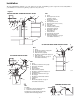
Installation The typical Installations in Figure 1 are only guides for selecting and installing system components. Contact Graymills or your distributor for assistance in planning a system to suit your needs.
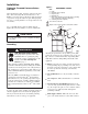
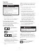
Installation Figure 2 Tightening Threaded Fasteners Before First Use KEY A H S T Y After unpacking the pump, and before using it for the first time, check and retorque all external fasteners. See the Service section for torque specifications. After the first day of operation, retorque the fasteners again. Although pump use varies, a general guideline is to retorque fasteners every two months.
Installation 2. Install an electrically conductive air exhaust hose (X) and connect the muffler to the other end of the hose. The minimum size for the air exhaust hose is 3/8” (10mm) ID. If a hose longer than 15 ft (4.57) is required, use a larger diameter hose. Avoid sharp bends or kinks in the hose. Mountings CAUTION The pump exhaust air may contain contaminants. If needed, ventilate to a remote area to reduce possible fluid contamination. See Air Exhaust Ventilation on this page. 3.
Installation of Remote Pilot Air Lines 1. Refer to Parts Drawings. Connect air line to pump as in preceding steps. 2. Connect 1/4” O.D. tubing to push type connectors (16) on underside of pump. 3. NOTE: by replacing the push type connectors, other sizes or types of fittings may be used. The new fittings will require 1/8” npt threads. 4. Connect remaining ends of tubes to external air signal. 5.
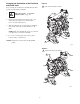
Figure 4 Changing the Orientation of the Fluid Inlet and Outlet Ports Torque to 80 to 90 in-lb (9 to 10 N-m). You can change the orientation of the fluid inlet and outlet ports by repositioning the manifolds. 1. Relieve the pressure. See Pressure Relief Procedure on page 10. 2. Remove the four manifold nuts (109), Figure 4. For double diaphragm pumps with 2 inlets/2 outlets, remove two bolts (105), Figure 5. 3.
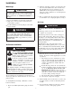
Operation Pressure Relief Procedure NOTE: If the inlet fluid pressure to the pump is more than 25% of the outlet working pressure, the ball check valves will not close fast enough, resulting in inefficient pump operation. WARNING PRESSURIZED EQUIPMENT HAZARD The equipment stays pressurized until pressure is manually relieved.
Maintenance Lubrication Tightening Threaded Connections The air valve is lubricated at the factory to operate without additional lubrication. If you want to provide additional lubrication, remove the hose from the pump air inlet and add two drops of machine oil to the air inlet every 500 hours of operation or every month. Before each use, check all hoses for wear or damage and replace as necessary. Check to be sure all threaded connections are tight and leak-free.
Troubleshooting Read Pressure Relief Procedure on page 10, and relieve the pressure before you check or service the equipment. Check all possible problems and causes before disassembling the pump. PROBLEM CAUSE SOLUTION Pump will not cycle, or cycles once and stops. Air valve is stuck or dirty. Use filtered air. Pump cycles at stall or fails to hold pressure at stall. Leaky check valves or o-rings. Replace. Worn check balls or duckbill valves or guides. Replace. Check ball wedged in guide.
Service Air Valve NOTE: Air Valve Repair Kit 784–90611 is available. Parts included in the kit are marked with a dagger ( ) in Fig. 6 and in the Parts Drawings and Lists. A tube of general purpose grease is supplied in the kit. Service the air valve as follows. See Fig. 6. 1. NOTES: Relieve the pressure. See Pressure Relief Procedure on page 10.
Service Figure 7 Ball or Duckbill Check Valves Split Manifold Pump NOTE: Use Fluid Section Repair Kit 784–90612 for Hytrel Diaphragm pumps and 784–90613 for PTFE Diaphragm pumps. General purpose grease and adhesive are supplied in the kits. 109 103 1. Relieve the pressure. See Pressure Relief Procedure on page 10. 139 202 139 2. Remove the top and bottom manifolds (102, 103). 3. Remove all parts shown with a dagger ( ). 4. Clean all parts, and replace worn or damaged parts. 5.
Service Diaphragms NOTE: Fluid Section Repair Kit 784–90612 for Hytrel and 784–90613 for PTFE Diaphragms are available. Parts included in the kit are marked with a double dagger ( ) in Fig. 8 and in the Parts Drawings and Lists. General purpose grease and adhesive are supplied in the kit. Service the diaphragms as follows. See Fig. 8. Disassembly Reassembly 1. 1. 2. Relieve the pressure. See Pressure Relief Procedure on page 10. NOTE: Make sure the lips of the u-cup face out of the center housing.
Service Figure 8 11 1 4 12 114 13 103 3 109 15 106 6 105 16 401 101 102 Included in Fluid Section Repair Kit 784–90612 or 784–90613 109 Install with lips facing out of center housing (11). Torque to 35 to 45 in-lb (4.0 to 5.1 N-m). Apply grease. The words “AIR SIDE” on diaphragm must face toward diaphragm shaft (15). Flat side of air-side diaphragm plate must face toward diaphragm shaft (15).
Parts Drawing Included in Air Valve Repair Kit 784–90611 111 106 grounding screw (acetal pump only) 109 Included in Fluid Section Repair Kit 784–90612 and 784–90613 12 103 * These parts are unique to the remote oper– ated air motor.
Dimensions FRONT VIEW 4.70 in. (119 mm) 1/2 npt(f) or bspt(f) Fluid Outlet * 5.01 in. (127 mm) 1/4 npt(f) Air Inlet 10.63 in. (270.0 mm) 9.94 in. (252.5 mm) 8.56 in. (217.4 mm) 7.75 in. (196.9 mm) 1.38 in. (35.1 mm) 6.12 in. (155.4 mm) SIDE VIEW 3.13 in. (79.5 mm) 1/2 npt(f) or bspt(f) Fluid Inlet * 3/4 npt(f) or bspt(f) Fluid Inlet * PUMP MOUNTING HOLE PATTERN 3/4 npt(f) or bspt(f) Fluid Outlet * Four 0.30 in. (7.6 mm) Diameter Slots 3/4 npt (f) or bspt(f) Fluid Inlet * 4.30 in. (109.
Performance Charts Fluid Outlet Pressure Air Consumption Test Conditions: Pump tested in water with inlet submerged. Air Consumption – scfm (cubic meters/min) Fluid Outlet Pressure – psi (MPa, bar) Test Conditions: Pump tested in water with inlet submerged. Fluid Pressure Curves A at 100 psi (0.7 MPa, 7 bar) air pressure B at 70 psi (0.48 MPa, 4.8 bar) air pressure C at 40 psi (0.28 MPa, 2.8 bar) air pressure (0.7, 7) (0.55, 5.5) (0.41, 4.1) B A C (0.28, 2.8) (0.14, 1.4) (7.6) (0.
1/2” Model DACT50 98/37/EC Machinery Directive 94/9/EC ATEX Directive (Ex II 2 G T6) EN 292 EN 1127–1 EN 13463–1 ISO 9614–1 0359 9–9–2005 Jerry Shields Graymills Corporation PRESIDENT (Print) 3705 N.