
Owner's manual


14
Service
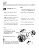
Ball or Duckbill Check Valves
NOTE: Use Fluid Section Repair Kit 784–90612 for
Hytrel Diaphragm pumps and 784–90613 for PTFE Dia-
phragm pumps. General purpose grease and adhesive are
supplied in the kits.
1. Relieve the pressure. See Pres-
sure Relief Procedure on page 10.
2. Remove the top and bottom manifolds (102, 103).
3. Remove all parts shown with a dagger ( ).
4. Clean all parts, and replace worn or damaged parts.
5. Reassemble the pump.
NOTE: Torque the manifold nuts (109) or bolts (105)
to 80 to 90 in-lb (9 to 10 N-m).
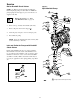
Inlet and Outlet for Pumps with Duckbill
Check Valves
Pumps with duckbill check valves are shipped with the
inlet manifold on bottom and the outlet manifold on the
top. To make the inlet manifold on the top and the outlet
manifold on the bottom, rotate each of the four duckbill
assemblies vertically 180 as shown below. This may be
necessary in applications where pump priming is problem-
atic.
202
201
139
Figure 7
103
202
202
201
301
139
201
301
202
201
139
109
109
Torque to 80 to 90 in-lb (9 to 10 N-m).
202
201
139
102
Split Manifold Pump
139
139
139