
Owner's manual


15
Service
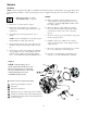
Diaphragms
NOTE: Fluid Section Repair Kit 784–90612 for Hytrel and 784–90613 for PTFE Diaphragms are available. Parts included
in the kit are marked with a double dagger ( ) in Fig. 8 and in the Parts Drawings and Lists. General purpose grease and
adhesive are supplied in the kit. Service the diaphragms as follows. See Fig. 8.
Disassembly
1. Relieve the pressure. See Pres-
sure Relief Procedure on page 10.
2. Remove manifolds (102 and 103) and fluid cov-
ers (101).
NOTE: Make sure all the check valve parts stay in
place.
3. Remove one of the fluid-side diaphragm plates (105)
(whichever one comes loose first when you use a
wrench on the hex of each), and pull the diaphragm
shaft out of the center housing (11).
4. Use a wrench on the flats of the diaphragm shaft (15)
to remove the other fluid-side diaphragm plate (105)
from the diaphragm shaft.
5. Remove the screws (106), remove the left (114) and
right (113) air covers, and remove all old gasket (12)
material from the ends of the center housing (11) and
the surfaces of the air covers.
6. Remove the diaphragm shaft u-cups (16) and pilot pin
o-rings (1).
7. Inspect all parts for wear or damage, and replace as
necessary.
Reassembly
1. Insert a diaphragm shaft u-cup (16) and a pilot pin
o-ring (1) into the bores of the center housing (11).
NOTE: Make sure the lips of the u-cup face out of the
center housing.
2. Line up the holes in the gasket (12) with the holes in
the end of the center housing (11), and use six screws
(106) to fasten an air cover (113 or 114) to the end of
the center housing (11). Torque the screws to 35 to 45
in-lb (4.0 to 5.1 N-m).
3. Position the exhaust cover (13) and o-ring (4) on the
center housing (11).
4. Repeat steps 1 and 2 for the other end of the center
housing and the remaining air cover.
5. Apply medium-strength (blue) Loctite or equivalent to
the threads of the fluid-side diaphragm plates (105).
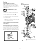
Install on one end of the diaphragm shaft (15) the
following parts (see proper order in Fig. 8): air-side
diaphragm plate (6) diaphragm (401), and fluid-side
diaphragm plate (105).
NOTE: The words “AIR SIDE” on the diaphragm
(401) and the flat side of the air-side diaphragm plate
(6) must face toward the diaphragm shaft (15)
6. Put grease on the diaphragm shaft (15), and carefully
(do not damage the shaft u-cups) run the diaphragm
shaft (15) through the center housing (11) bore.
7. Repeat step 5 for the other end of the diaphragm shaft
(15), and torque the fluid-side diaphragm plates (105)
to 80 to 90 in-lb (9 to 10 N-m) at 100 rpm maximum.
8. Install the muffler (3).
9. Make sure all the check valve parts are in place.
10. Reinstall the fluid covers (101) and manifolds (102 and
103), and torque the fluid cover and manifold nuts
(109) to 80 to 90 in-lb (9 to 10 N-m).