
Owner's manual


8
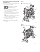
Installation of Remote Pilot Air Lines
1. Refer to Parts Drawings. Connect air line to pump as in
preceding steps.
2. Connect 1/4” O.D. tubing to push type connectors (16)
on underside of pump.
3. NOTE: by replacing the push type connectors, other
sizes or types of fittings may be used. The new fittings
will require 1/8” npt threads.
4. Connect remaining ends of tubes to external air signal.
5. NOTE: the air pressure at the connectors must be at
least 30% of the air pressure to the air motor for the
pump to operate.
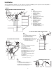
Fluid Suction Line
Ground the fluid system. Read Grounding on page 6. The
fluid inlet port is 1/2” or 3/4”. At inlet fluid pressure
greater than 15 psi (0.1 MPa, 1 bar), diaphragm life will be
shortened.
a. The fluid pressure can be controlled in either of
two ways. To control it on the air side, install an
air regulator (G). To control it on the fluid side,
install a fluid regulator (J) near the pump fluid
outlet (see Fig. 1).
b. Locate one bleed-type master air valve (B) close
to the pump and use it to relieve trapped air. Read
the WARNING on page 7. Locate the other master
air valve (E) upstream from all air line accessories
and use it to isolate them during cleaning and
repair.
c. The air line filter (F) removes harmful dirt and
moisture from the compressed air supply.
6. Install an electrically conductive, flexible air hose (C)
between the accessories and the 1/4 npt(f) pump air
inlet. Use a minimum 1/4” (6.3 mm) ID air hose.
Screw an air line quick disconnect coupler (D) onto the
end of the air hose (C), and screw the mating fitting
into the pump air inlet snugly. Do not connect the
coupler (D) to the fitting yet.
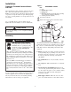
Fluid Pressure Relief Valve
CAUTION
Some systems may require installation of a pressure relief
valve at the pump outlet to prevent overpressurization
and rupture of the pump or hose. See Fig. 3.
Thermal expansion of fluid in the outlet line can cause
overpressurization. This can occur when using long fluid
lines exposed to sunlight or ambient heat, or when
pumping from a cool to a warm area (for example, from
an underground tank).
Overpressurization can also occur if the pump is being
used to feed fluid to a piston pump, and the intake valve
of the piston pump does not close, causing fluid to back
up in the outlet line.
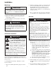
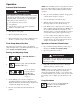
F
igure 3
Connect fluid inlet line here.
Install valve between fluid inlet and outlet ports.
Connect fluid outlet line here.
CAUTION
For solenoid operation, the pump must exhaust through
the solenoid. Failure to exhaust through solenoid could
cause the diaphragms to fail..