Installation Guide
TABLE OF CONTENTS Installation Basics......................................................................................3-4 Starter Course.............................................................................................. 5 Dual Offset Installation Method................................................................... 6 Windows and Doors..................................................................................7-8 Soffits/Termination...................................................
INSTALLATION BASICS Before you begin, take the time to read this entire guide to clearly understand the requirements and steps to follow for proper installation. WARNING: The specifications in the guide apply to the installation of Grayne Engineered Shake and Shingle to exterior wall surfaces only. Before you begin, consult your local building code for the installation requirements for shingle siding, breather membrane (housewrap), caulking, etc.
INSTALLATION BASICS 1/8" Leave a minimum of 1/8" clearance at all openings and stops to allow for normal expansion and contraction. When installing in temperatures below 40° F/4.4° C, increase minimum clearance to 3/8" (9.5mm). When lapping panels, leave 1/8" gap at nailing hem (FIG 1). When installing a siding panel, push up from the bottom until the lock is fully engaged with the piece below it. The panels should not be under tension or compression when they are fastened.
STARTER COURSE If your using Grayne Engineered Shingle or Shakes for an entire wall, start by installing a starter strip. Determine the lowest point of the wall that will be sided; from that point measure up 1/4" (6.4mm) less than the width of the starter strip, use a chalk line to make a straight level reference mark (Fig 3). This location will position the top of the starter (Fig 4).
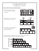
DUAL OFFSET INSTALLATION METHOD Correct Installation Dual offset installation methods ensures shingles will have proper “side laps”. When starting a course, panels will be cut between the “cut marks”. Square Incorrect Installation Triangle y yÅ The installed course should always end on the “panel end mark” of the course below.
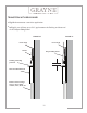
WINDOWS AND DOORS If not using a window with a built in “J” pocket, we recommend using Kleer Konceal Trim Board (or equivalent too) around windows and doors. Use proper flashing methods to avoid water infiltration (Fig 5). FIGURE 5 Approx. 10" Approx. 10" Header Approx.
WINDOWS AND DOORS (cont.) Flashing should extend beyond face nails and/or trim nailing locations (Fig 6 & 7). Shims maybe required to correctly position the siding panel projection to the wall. Shim thickness depends on location of custom trimming of the panel(s) for window sills and window or door headers (Fig 7).
SOFFITS/TERMINATION OPTION 1 When using Kleer Konceal Trim, shims maybe required to correctly position the siding panel projection to the wall when custom trimming panel/s is required. Shim thickness depends on location of custom trimming of the panel/s (Fig 8). Face nail Grayne Panel into shim. OPTION 2 Place a trim/fascia board over the installed shingles. This is typically called “capping”.
TRANSITION WITH BELLY-BAND Fig 10 demonstrates a transition application. In Fig 11 you will have up to 3/4" gap between the flashing and butt-end of the Grayne Siding Panel. FIGURE 10 FIGURE 11 House wrap House wrap Starter Grayne Siding Panel Flashing extending past trim 3/4" Kleer Trim Board/Fascia Exterior wall coverings such as; stucco, fiber cement, stone, brick, etc.
TRANSITION FROM HARDBOARD LAP SIDING Below demonstrates a transition application from Hardboard Style Lap Siding.
OUTSIDE/INSIDE CORNER Recommend using Kleer Konceal Cornerboards or equivalent. Refer to manufacturers installation guide for additional information. All corner sheathing must be properly flashed prior to installing cornerboards (Fig 12). Outside and Inside corners must be installed prior to installing the Grayne Siding Panel. Inside corners you will need to rip-saw along the length of one of the trim boards the board thickness, to achieve an even reveal surface on each side (Fig 13).