Chariot Brutus GBKW2552S, GBKH2752S GBKW2561S, GBKH2761S TCU20866 C5 OPERATOR’S MANUAL 200315 03/06/2006
INTRODUCTION Introduction Using Your Operator’s Manual This manual is an important part of your machine and should remain with the machine when you sell it. Use the safety and operating information in the machine operator’s manual to operate and service the machine safely and correctly. WARNING: The Engine Exhaust from this product contains chemicals known to the State of California to cause cancer, birth defects or other reproductive harm.
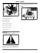
SAFETY LABELS The operator’s manual also explains any potential safety hazards whenever necessary in special safety messages that are identified with the word, CAUTION, and the safety-alert symbol. DANGER MODEL NUMBER (POWER UNIT) (A): __ __ __ __ __ __ __ __ __ __ __ __ __ __ __ __ __ SERIAL NUMBER (POWER UNIT) (A): __ __ __ __ __ __ __ __ __ __ __ __ __ __ __ __ __ ENGINE MODEL NUMBER(B): To avoid injury from rotating blades, stay clear of deck edge.
SAFETY LABELS DANGER DANGER Do not mow without discharge chute or entire grass catcher in place. • Cigarettes, flames or sparks could cause battery to explode. Always shield eyes and face from battery. Do not charge or use booster cables or adjust post connections without proper instruction and training. • Contains sulfuric acid. Avoid contact with the skin, eyes or clothing. In event of accident, flush with water and call a physician immediately. Keep out of reach of children.
SAFETY LABELS WARNING • Read operator’s manual • Keep shields in place • Never carry riders • Keep people a safe distance away • Maintain all safety devices • Before leaving machine: • Stop engine • Set park brake • Remove key WARNING To avoid injury from rotating belts, keep all shields and guards in place.
SAFETY Emission Control System Certification Label Preparation NOTE: Tampering with emission controls and components by unauthorized personnel may result in severe fines or penalties. Emission controls and components can only be adjusted by EPA and/or CARB authorized service centers. Contact your Great Dane Equipment Retailer concerning emission controls and component questions. • Evaluate the terrain to determine what accessories and attachments are needed to properly and safely perform the job.
SAFETY • Be aware of the mower discharge direction and do not point it at anyone. Parking Safely • Do not operate the machine while under the influence of alcohol or drugs. 1.Stop machine on a level surface, not on a slope. • Use care when loading or unloading the machine into or off of a trailer or truck. 3.Disengage mower blades. 2.Move motion control levers out to the neutral lock position. • Use care when approaching blind corners, shrubs, trees, or other objects that may obscure vision. 4.
SAFETY Protect Children • Keep all movement on slopes slow and gradual. Do not make sudden changes in speed or direction, which could cause the machine to roll over. • Use extra care while operating machine with grasscatchers or other attachments, they can affect stability of the machine. Do not use on steep slopes. • Do not mow near drop-offs, ditches, embankments, or bodies of water. The machine could suddenly roll over if a wheel goes over the edge or the edge caves in.
SAFETY Keep Riders Off signals according to local regulations. Extra flashing warning lights may need to be installed. • Only allow the operator on the machine. Keep riders off. • Riders on the machine or attachment may be struck by foreign objects or thrown off the machine causing serious injury. • Riders obstruct the operator’s view resulting in the machine being operated in an unsafe manner. Checking Wheel Hardware • A serious accident could occur causing serious injury if wheel hardware is not tight.
SAFETY • Shut off fuel while storing or transporting. Do not store fuel near flames or drain indoors. • Do not store machine near an open flame or source of ignition, such as a water heater or furnace. • Park machine on level ground. Never allow untrained personnel to service machine. Understand service procedure before doing work. • Check fuel lines, tank, cap, and fittings frequently for cracks or leaks. Replace if necessary.
OPERATING • Never remove the fuel tank cap or add fuel with the engine running. Allow engine to cool before refueling. Handling Waste Product and Chemicals • Never add fuel to or drain fuel from the machine indoors. Move machine outdoors and provide adequate ventilation. • Clean up spilled fuel immediately. If fuel is spilled on clothing, change clothing immediately. If fuel is spilled near machine, do not attempt to start the engine but move the machine away from the area of spillage.
OPERATING • Be careful not to spill fuel on machine. Fuel may damage surface. Wipe up spilled fuel immediately. Mounting and Dismounting Machine Safely • Prolonged exposure to sunlight will damage the hood surface. Operator Station Controls A- Motion Control Levers B- Park Brake Lever C- Seat Adjustment Lever D- Hourmeter Do not step on the mower deck when mounting and dismounting the machine. Mount the machine from the front using the foot plate (A).
OPERATING Adjusting Seat Using Seat Belt Front-to-Back Adjustment 1.Park machine safely. (See Parking Safely in the SAFETY section.) CAUTION: Avoid injury! Always wear seat belt when operating machine with non-folding Roll-Over Protective Structure (ROPS) or folding ROPS in upright position. Do not jump from machine if machine tips. 2.Sit on the operator seat. •If folding ROPS must be folded to operate in a low clearance area, do not use seat belt.
OPERATING 1.Park machine safely. (See Parking Safely in the SAFETY section.) 2.Move the mower deck lift lever (A) to the transport position (D). 3.Position the HOC adjustment pin (C) in the proper hole for the desired height-of-cut. 4.Push ROPS into upright position. 5.Install drilled pin (B) into holes on left and right side of ROPS, and secure in place with spring pins (A). 4.Pull back and hold the mower deck lift lever (A) and release the transport position lock lever (B). 6.
OPERATING NOTE: The rear anti-scalp wheels are located under the rear of the mower deck. Testing Safety Systems CAUTION: Avoid injury! Engine exhaust fumes contain carbon monoxide and can cause serious illness or death. Move the machine to an outside area before running the engine.Do not run an engine in an enclosed area without adequate ventilation.• •Connect a pipe extension to the engine exhaust pipe to direct the exhaust fumes out of the area.
OPERATING Testing Seat Switch Locking Park Brake: Procedure 1: 1.Sit on the operator seat with the motion control levers in the neutral detent position (standard levers) or neutral lock position (optional “over the lap” levers). CAUTION: Avoid injury! If the engine should stop while operating on an incline, the mower can free wheel. If this should occur:•lock the park brake, 2.Unlock the park brake. •start the engine, 3.Push PTO knob down to disengage. •unlock the park brake, 4.
OPERATING Using the Key Switch Using the Throttle Lever NOTE: Machine will only start if the following conditions exist: • Park brake is locked. • PTO is disengaged. • Motion control levers are in the neutral detent position (standard levers) or neutral lock position (optional “over the lap” levers). A STOP B • Push throttle lever (A) all the way forward to the full-throttle detent position (B) when mowing.
OPERATING Using the Choke switch disengaged and the park brake locked to start the engine. Engage Choke: Neutral Lock Position - Optional “Over the Lap” Levers • Pull choke knob (A) out. Disengage Choke: Picture Note: Motion control levers (A) shown in the neutral lock position. • Push choke knob (A) in. • Motion control levers must be in the neutral lock position, the PTO switch disengaged and the park brake locked to start the engine.
OPERATING Reverse: Forward and Reverse Motion: CAUTION: Avoid injury! Children or bystanders can be injured or killed by moving machine and rotating blades. Before traveling forward or rearward:• •Carefully check area around machine. •Disengage mower before backing up. 1.Move throttle lever to the full-throttle position. 2.Unlock the park brake. 3.Optional “over the lap” levers: Move both motion control levers from the neutral lock position inward to the neutral position. 4.
OPERATING Sharp Left Turn: 4.Push PTO knob (A) down to disengage PTO. • Push right control lever forward and pull left control lever rearward at the same time. 5.Move throttle lever to set engine speed: • Cold engine: Set throttle lever at the 1/2- to 3/4-throttle position. • Warm/Hot engine: Set throttle lever to the 1/2-throttle position. Sharp Right Turn: 6.Position choke knob (D): • Cold engine: Pull knob up and hold in choke position.
OPERATING Engaging Mower move throttle to slow position. CAUTION: Avoid injury! Clear mowing area of all bystanders when operating this machine. A STOP Thrown objects could cause serious injury or death. Keep hands and feet away from blades and discharge opening. Do not mow in reverse unless absolutely necessary. IMPORTANT: Avoid damage! To help prevent damage to PTO clutch: • Do not engage PTO with throttle in the fast position. 1.Adjust mower deck to desired cutting height. 5.
SERVICE INTERVALS • Mow tall or wet grass twice. Cut grass at half desired height – then cut at desired height. • Travel slow when mowing tall, thick or wet grass. • Check wheel nut torque. • Check and adjust (as needed) park brake. • Remove debris from the underside of the mower deck. • Avoid damaging grass by slipping or skidding machine drive wheels. Practice smooth control lever movements. • When performing sharp turns, do not allow inside machine drive wheel to stop and twist on grass.
SERVICE LUBRICATION Service Lubrication Grease IMPORTANT: Avoid damage! The recommended grease is effective within an average air temperature range of -29 to 135 degrees C (-20 to 275 degrees F). If operating outside that temperature range, contact your servicing dealer for a special-use grease. Use a general all-purpose grease with an NLGI grade No.2 rating. Wet or high speed conditions may require use of a special-use grease. Contact your Servicing dealer for information. Spray Lubricant 3.
SERVICE ENGINE 6.Grease traction drive belt tension arm pivot (G). 9.Lubricate hydraulic pump control arms (N). 10.Lubricate control lever pivot shaft (O). 11.Lubricate seat platform hinges (P). 12.Lubricate throttle control cable (Q). 13.Lubricate choke control cable (R).
SERVICE ENGINE Checking Engine Oil Level CAUTION: Avoid injury! Touching hot surfaces can burn skin. The engine, components, and fluids will be hot if the engine has been running. Allow the engine to cool before servicing or working near the engine and components. IMPORTANT: Avoid damage! Failure to check the oil level regularly could lead to serious engine problems if oil level is low: • Check oil level before operating. • Keep oil level between the FULL and the ADD marks.
SERVICE ENGINE Cleaning Engine Air Intake Screen and Fan your machine for the complete procedure. Adjusting Carburetor CAUTION: Avoid injury! Compressed air can cause debris to fly a long distance.• •Clear work area of bystanders. •Wear eye protection when using compressed air for cleaning purposes. •Reduce compressed air pressure to 210 kPa (30 psi). IMPORTANT: Avoid damage! An obstructed air intake screen can cause engine damage due to overheating.
SERVICE TRANSMISSION IMPORTANT: Avoid damage! Contamination of hydraulic fluid could cause transmission damage or failure. Do not open oil reservoir cap unless absolutely necessary. Service Transmission Hydraulic Oil Severe or unusual conditions may require a more frequent service interval. Use only 5W-50 or 15W-50 all synthetic oil. Checking Hydraulic Oil Level 1.Park machine safely. (See Parking Safely in the SAFETY section.
SERVICE TRANSMISSION Removing and Installing Traction Drive Belt CAUTION: Avoid injury! Engine exhaust fumes contain carbon monoxide and can cause serious illness or death. Move the machine to an outside area before running the engine.Do not run an engine in an enclosed area without adequate ventilation. •Connect a pipe extension to the engine exhaust pipe to direct the exhaust fumes out of the area. 1.Park machine safely. (See Parking Safely in the SAFETY section.) 2.Remove mower deck drive belt.
SERVICE TRANSMISSION Check Neutral Creep CAUTION: Avoid injury! Engine exhaust fumes contain carbon monoxide and can cause serious illness or death. Move the machine to an outside area before running the engine. Do not run an engine in an enclosed area without adequate ventilation. •Connect a pipe extension to the engine exhaust pipe to direct the exhaust fumes out of the area. •Allow fresh outside air into the work area to clear the exhaust fumes out.
SERVICE TRANSMISSION NOTE: If the machine travels to the left, adjust the right speed drift screw (A). If the machine travels to the right, adjust the left speed drift screw (B). 3.Adjust the appropriate speed drift screw (A or B) as follows: a.Loosen jam nut (C or D). b.Adjust the screw (A or B) one turn clockwise. c.Tighten the jam nut (C or D). 4.Lower the seat platform. 5.Perform Check Maximum Speed Drift procedure to check adjustment. Repeat the adjustment procedure as needed.
SERVICE TRANSMISSION Hydraulic System Hose Routing A- Hydraulic Reservoir B- Oil Filter C- Right Hydraulic Pump D- Right Wheel Motor E- Left Wheel Motor F - Left Hydraulic Pump Service Transmission - 30
SERVICE STEERING & BRAKES Hydraulic System Schematic J - Left Wheel Motor A- Control Input Shaft K- Left Hydraulic Pump B- Pump Block L - Oil Filter C- Charge Pump M- Hydraulic Reservoir D- Charge System Check Valve E- Right Hydraulic Pump F - Manual Bypass (Free-Wheel) Valve Service Steering & Brakes G- Right Wheel Motor H- Cooling Orifice I - Charge Relief Valve Service Steering & Brakes - 31
SERVICE STEERING & BRAKES Removing and Installing Front Caster Wheels Removing 1.Park machine safely. (See Parking Safely in the SAFETY section.) CAUTION: Avoid injury! The machine may fall or slip from an unsafe lifting device or supports, injuring anyone beneath it. • Remove key before raising machine. • Use a safe lifting device rated for the load to be lifted. • Lower machine onto stable supports or jack stands and block wheels before servicing. 2.Lift front of machine with a safe lifting device. 3.
SERVICE STEERING & BRAKES 3.Remove cotter pin (B). 4.Turn castle nut (C) 1/4 turn clockwise. 5.Install a new cotter pin. Do not loosen the castle nut to align cotter pin hole, tighten to align. 6.Replace dust cover. 7.Test machine to determine if shimmy is still present. Repeat adjustment as necessary. Servicing Caster Spindle Bearings 1.Park machine safely. (See Parking Safely in the SAFETY section.) 3.
SERVICE MOWER • To mount in the high position, mount the levers to the top four holes in the mounting bracket. • Loosen cap screws (C). • To mount in the low position, mount the levers to the bottom four holes in the mounting bracket. • Slide both levers forward or rearward to desired position on control arm until levers are aligned. • Tighten cap screws. Checking and Aligning Motion Control Levers Optional Over the Lap Levers Adjusting Park Brake Check Alignment: 1.Park machine safely.
SERVICE MOWER Removing Foot Plate 1.Park machine safely. (See Parking Safely in the SAFETY section.) 3.Remove knob (A). 4.Remove belt shield (B). Installing Belt Shields 1.Install belt shield (B). 2.Raise foot plate (A) using hole (B). 2.Install knob (A). Leveling Mower Deck CAUTION: Avoid injury! Rotating blades are dangerous. Before adjusting or servicing mower: •Remove ignition key or disconnect battery negative (-) cable to prevent engine from starting accidently.
SERVICE MOWER Picture Note: Discharge chute raised for photo clarity. 3.Position right mower blade (A) (discharge side) in the side-to-side position. 4.Measure from outside blade tip to the ground. • The difference between both measurements should be no greater than 3 mm (1/8 in.). 5.If side-to-side level is not within specifications, an adjustment is necessary. • The height (C) of the rear blade tip should be 3-6 mm (1/8-1/4 in.) higher than the front blade tip. 5.
SERVICE MOWER Checking and Adjusting Cutting Height • To lower deck, turn nut (C) counterclockwise. • To raise deck, turn nut (C) clockwise. CAUTION: Avoid injury! Rotating blades are dangerous. Before adjusting or servicing mower: •Remove ignition key or disconnect battery negative (-) cable to prevent engine from starting accidently. •Always wear gloves when handling mower blades or working near blades. 4.Tighten jam nut (A).
SERVICE MOWER CAUTION: Avoid injury! Fingers and hands can be pinched or crushed. Keeps hands clear of sheave and belt pinch points when servicing belt. 5.Remove mower deck drive belt (B). 4.Loosen jam nut (A). 5.Check the mower deck drive belt (B) tension. The belt should deflect a maximum of 13 mm (1/2 in.) when a force of 4.5 kg (10 lb) is applied to the center of the longest span. When properly adjusted, there would be approximately a 2 mm (1/16 in.) gap between the spring coils.
SERVICE MOWER IMPORTANT: Avoid damage! When replacing mower blades, always use genuine Great Dane Service Parts. CAUTION: Avoid injury! Mower blades are dangerous! •Always wear gloves while working on blades. NOTE: Only replace blades. Never straighten or weld them. •Always wear safety eye protection when grinding. Checking Mower Blades 1.Park machine safely. (See Parking Safely in the Safety Section). • Sharpen blades with grinder, hand file, or electric blade sharpener. 2.
SERVICE ELECTRICAL cancer and reproductive harm. Wash hands after handling. Service the Battery Safely CAUTION: Avoid injury! The battery produces a flammable and explosive gas. The battery may explode: •Do not smoke near battery. •Wear eye protection and gloves. •Do not allow direct metal contact across battery posts. •Remove negative cable first when disconnecting. •Install negative cable last when connecting. Removing and Installing the Battery Removing: 1.Park machine safely.
SERVICE ELECTRICAL Installing: 2.Connect the positive battery cable (D) first, then the negative cable (B). IMPORTANT: Avoid damage! Electric charge from booster battery can damage machine components. Do not install negative booster cable to machine frame. Install only to the engine block. 3.Apply petroleum jelly or silicone spray to the terminals to prevent corrosion. Install negative booster cable away from moving parts in the engine compartment, such as belts and fan blades. 1.
SERVICE ELECTRICAL Wiring Schematic Service Electrical - 42
SERVICE MISCELLANEOUS 2.Allow engine to cool. Service Miscellaneous 3.Remove any trash from area around fuel tank cap. Using Proper Fuel 4.Remove fuel tank cap slowly to allow any pressure built up in tank to escape. Use regular grade unleaded fuel with an octane rating of 87 octane or higher. Fuel blends containing up to 10% ethanol or up to 15% MTBE reformulated fuel are acceptable. Do not use fuel or additives containing methanol as engine damage can occur.
TROUBLESHOOTING Cleaning and Repairing Plastic Surfaces Your authorized dealer has the professional materials needed to properly remove surface scratches from any plastic surfaces, do not attempt to paint over marks or scratches in plastic parts. IMPORTANT: Avoid damage! Improper care of machine plastic surfaces can damage that surface: • Do not wipe plastic surfaces when they are dry. Dry wiping will result in minor surface scratches. • Use a soft, clean cloth (bath towel, diaper, automotive mitt).
TROUBLESHOOTING Engine If Check Engine Will Not Start or Is Hard to Start Motion control levers not in the neutral detent (or neutral lock) position. If Check Engine Lacks Power Plugged air intake system. Plugged fuel filter. Improper type of fuel. Drain tank and fill with correct fuel. Park brake lever unlocked. Clean cooling fins to help prevent overheating. Key switch not in proper position. PTO engaged. Loose or corroded starter cable connections. Replace spark plug.
TROUBLESHOOTING If Check If Check PTO Clutch Does Not Engage Blown 20-amp fuse (main power circuit). Machine Will Not Follow a Straight Path Steering tracking out of adjustment. Machine Moves to the Left or Right With Engine Running and Transmission in Neutral Pump linkage (neutral position) out of adjustment. Faulty PTO switch. Faulty PTO clutch. Loose PTO clutch connections. Starter Turns Slowly Loose or corroded battery or ground connections. Low battery power - charge battery.
STORAGE for longer than 60 days. Storage 1.Change engine oil and filter while engine is warm. Storing Safety 2.Service air filter if necessary. 3.Clean debris from engine air intake screen. CAUTION: Avoid injury! Fuel vapors are explosive and flammable. Engine exhaust fumes contain carbon monoxide and can cause serious illness or death: •Run the engine only long enough to move the machine to or from storage.
ASSEMBLY • Cut plastic tie straps fastening the front wheels to the shipping crate. Install Motion Control Levers • Cut plastic tie straps holding the discharge chute up. 1.Remove hardware from control arms. • Cut plastic tie straps securing the motion control levers to the machine. Check Fluid Levels NOTE: Refer to the Service sections of the operator’s manual for information regarding check locations and proper fluid levels. • Check engine oil level. • Check hydraulic oil level.
ASSEMBLY Install ROPS 1.Remove and retain the two locknuts and cap screws securing the flanges at the rear of the seat frame to the machine. 1.Support rear of bumper with wooden blocks or jack. 2.Loosen nut (A) securing the rear battery hold-down rod and disengage hooked end (B) from bumper. 3.Remove all bumper mounting bolts and retaining hardware except for the lower left cap screw (C) at each side of the machine. Discard any assembly washers, retain bolts and locknuts for later use. 2.
SPECIFICATIONS Check Safety System CAUTION: Avoid injury! Machine component is heavy. Use a safe lifting device or get an assistant to help lift and hold component into place for installation. For a complete checkout procedure of the safety interlock system, see Testing the Safety Interlock System in the Operating section. Initial Adjustments NOTE: Using a tapered drift will aid in the alignment of mounting holes and ease installation of cap screws.
GETTING QUALITY SERVICE Inflation Rear (Maximum) . . . . . . . . . . . . . . . . . . . . .69-97 kPa (10-14 psi) Wheel Nut Torque . . . . . . . . . . . . . . . . . . . . . . . . . . . . . 100 N•m (75 lb-ft) Getting Quality Service Capacities Service Literature Fuel Tank . . . . . . . . . . . . . . . . . . . . . . . . . . . . . . . . . . . . . . . 30.2 L (8 gal) If you would like to order a copy of the Parts Catalog or Operator Manual for this machine, contact your dealer.
ENGINE AND RELATED COMPONENTS - KAWASAKI ENGINE AND RELATED COMPONENTS - KAWASAKI - 52
ENGINE AND RELATED COMPONENTS - KAWASAKI Ref. No. 1 2 3 4 5 6 7 8 9 10 11 12 13 14 15 16 17 18 19 20 21 22 Part No. 14M7166 19M7897 200318 GDA10017 D18056 D14208 19H2531 TCA16240 D18145 D18379 M76926 M78480 M136651 GD10128 H137328 03M7184 D22236 12M7065 14M7273 200316 03M7017 14M7518 Description LOCK NUT SCREW PULLEY CLUTCH SPACER LOCK WASHER CAP SCREW DRAIN VALVE SHAFT KEY CLAMP TUBE TIE BAND GASKET MUFFLER LOCK NUT BOLT ANGLE LOCK WASHER NUT BRACKET BOLT FLANGE NUT Qty.
ENGINE AND RELATED COMPONENTS - KOHLER 27 HP ENGINE AND RELATED COMPONENTS - KOHLER 27 HP - 54
ENGINE AND RELATED COMPONENTS - KOHLER 27 HP Ref. No. 1 2 3 4 5 6 7 8 9 10 11 12 13 14 15 16 17 18 Part No. 14M7396 19M8317 200311 GDA10122 GDU10312 D14208 D24022 TCA15389 D18145 230687 M78480 M132446 D28121 12M7065 14M7273 200316 03M7017 14M7518 Description LOCK NUT SCREW PULLEY CLUTCH SPACER LOCK WASHER BOLT HOSE SHAFT KEY FITTING PLUG TIE BAND GASKET MUFFLER LOCK WASHER NUT BRACKET BOLT FLANGE NUT Qty.
FUEL DELIVERY SYSTEM COMPONENTS Ref. No. 1 2 3 4 5 6 7 8 9 10 11 12 13 Part No. 181251 M88753 R56101 GDA10012 D18144 GDU10026 M63277 E53830 M63277 N10213 D14235 GDU10028 24H1776 Description FILLER CAP HOSE CLIP FUEL TANK BUSHING FUEL PICKUP LOCK NUT CLAMP LOCK NUT LOCK NUT BOLT STRAP WASHER FUEL DELIVERY SYSTEM COMPONENTS - 56 Qty. 1 1 2 1 1 1 2 2 2 1 2 2 2 Remarks (INCLUDES M145626) 7.925 MM (5/16") 7.925 MM (5/16") 7.925 MM (5/16") 7.925 MM X 63.5 MM (5/16"X 2-1/2") 5/16" X 47/64" X .
OVER THE LAP CONTROL ASSEMBLY Ref. No. 1 2 3 4 5 6 7 8 9 10 Part No. TCU14989 M131171 GDU10047 19M8320 14M7518 03M7195 M85516 TCU13271 GDU10275 37M7059 Description TUBE GRIP STRAP SCREW FLANGE NUT BOLT LOCK NUT ARM COVER SCREW OVER THE LAP CONTROL ASSEMBLY - 57 Qty.
ELECTRICAL AND RELATED COMPONENTS ELECTRICAL AND RELATED COMPONENTS - 58
ELECTRICAL AND RELATED COMPONENTS Ref. No. 1 2 3 4 5 6 7 8 9 10 11 12 13 14 15 16 17 18 19 20 21 22 23 24 25 26 27 28 29 30 31 32 33 34 35 36 37 38 39 ** 40 41 42 Part No.
CONSOLE AND CONTROL ASSEMBLY CONSOLE AND CONTROL ASSEMBLY - 60
CONSOLE AND CONTROL ASSEMBLY Ref. No. 1 2 3 4 5 6 7 8 9 10 11 12 13 14 15 16 17 18 19 20 21 22 23 24 25 26 27 28 29 30 31 32 33 34 35 36 37 38 39 40 41 42 43 Part No.
HYDROSTATIC DRIVE SYSTEM COMPONENTS Hydrostatic drive system Components - 62
HYDROSTATIC DRIVE SYSTEM COMPONENTS Ref.No. 1 2 3 4 5 6 7 8 9 10 11 12 13 14 15 16 17 18 19 20 21 Part No. D24028 D18379 D14197 M86863 D28026 GDA10089 D24026 MT2119 200313 200312 D19000 GDA10022 TCA15373 D18207 GDA10137 GDA10100 AZ45116 M78480 Description FITTING BULK HOSE BULK HOSE BULK HOSE BULK HOSE BULK HOSE BULK HOSE CLAMP FITTING TEE FITTING HOSE HYDRAULIC HOSE FITTING NUT PUMP PUMP SEAL KIT DIPSTICK HYDRAULIC RESERVOIR KEY OIL FILTER WHEEL MOTOR GASKET KIT TIE BAND Qty.
TRACTION DRIVE AND BRAKES TRACTION DRIVE AND BRAKES - 64
TRACTION DRIVE AND BRAKES Ref. No. 1 2 3 4 5 6 7 8 9 10 11 12 13 14 15 16 17 18 19 20 21 22 23 24 25 26 27 28 29 30 31 32 33 34 35 36 37 38 39 40 41 42 43 44 45 46 47 48 49 50 51 52 53 54 55 56 57 58 59 60 61 62 63 Part No.
HYDRAULIC SCHEMATIC Hydraulic Schematic - 66
SEAT COMPONENTS Ref. No. 1 2 3 4 5 6 7 8 9 10 11 12 13 14 15 16 17 Part No. 192068 181749 181461 181074 24H1887 TCU17356 200324 135139 K40003 03M7184 E83830 14M7396 M63277 14M7518 GDA10136 19M7786 181572 960703 960079 964025 Seat Components - 67 Description SUSPENSION SEAT KIT ARM REST SEAT SWITCH WASHER PAD SEAT PLATE (YELLOW) BOLT LOCK NUT BOLT CLAMP LOCK NUT LOCK NUT FLANGE NUT BRACKET SCREW SEAT BELT FLAT WASHER BOLT LOCK NUT Qty.
FRAME ASSEMBLY
FRAME ASSEMBLY Ref. No. 1 2 3 4 5 6 7 8 9 10 11 12 13 14 15 16 17 18A 18B 19 20 21 22 Part No. 200338 14M7396 E53830 GDU10222 03M7199 H137329 03M7197 JD7844 200329 135139 964022 GDU10165 GDU10164 03M7017 03M7085 14M7518 19M7865 TCU20372 TCU20695 GDU10285 GDU10184 GDU10170 191257 Description Qty.
FRONT CASTER ASSEMBLY FRONT CASTER ASSEMBLY - 70
FRONT CASTER ASSEMBLY Ref. No. 1 2 3 4 5 6 7 8 9 10 11 12 13 14 15 16 17 18 19 Part No. 200334 TCU14490 AA21840 TCU13871 TCA13769 19M7978 14M7276 TCU13454 E14625 JD8933 145553 24H180 11M7083 A12188 TCU14490 JD7844 TCU13604 TCU15970 AM30795 Description YOKE ROUND RETAINER BALL BEARING SPACER TIRE AND WHEEL ASSEMBLY CAP SCREW NUT SPACER SEAL BEARING CONE BEARING CUP WASHER COTTER PIN LOCK NUT ROUND RETAINER LUBRICATION FITTING RIM TIRE TIRE VALVE STEM Qty.
ROPS Ref. No. 1 Part No. TCA16051 Description ROPS 1 NOTES ROPS - 72 Qty.
NOTES Notes - 73
SPINDLE ASSEMBLY SPINDLE ASSEMBLY - 74
SPINDLE ASSEMBLY Ref. No. 1 2 3 4 5 6 7 8 9 10 11 12 13 14 Part No. 200041 200046 200042 200044 200043 200045 D13055 D18209 D18084 D18211 D13024 967347 960502 D18055 GDU10230 GDU10231 GDU10232 200047 Description Spindle Assembly Ball Bearing Housing Spacer Shaft, Spindle Bolt Nut, Pulley (Special) Pulley, Cutter Housing, 48" Deck Pulley, Cutter Housing, 52" Deck Pulley, Cutter Housing, 61" Deck Spacer, Pulley Bolt, Blade Nut Spacer, Blade Bolt 16.5" Blade, 48" Deck 18.0" Blade, 52" Deck 21.
DECK LIFT ASSEMBLY DECK LIFT ASSEMBLY - 76
DECK LIFT ASSEMBLY Ref. No. 1 2 3 4 5 6 7 8 9 10 11 12 13 14 15 16 17 18 19 20 21 22 23 24 25 26 27 28 29 30 31 32 33 34 35 36 37 Part No.
48" AND 52" CUTTING DECK 48" AND 52" CUTTING DECK - 78
48" AND 52" CUTTING DECK Ref. No. 1 2 3 4 5 6 7 8 9 10 11 12 13 14 15 16 17 18 19 20 21 22 23 24 25 26 27 28 29 30 31 32 33 34 35 36 37 38 39 40 41 42 43 44 45 46 47 48 49 50 51 Part No.
61" CUTTING DECK 61" CUTTING Deck - 80
61" CUTTING DECK Ref. No. 1 2 3 4 5 6 7 8 9 10 11 12 13 14 15 16 17 18 19 20 21 22 23 24 25 26 27 28 29 30 31 32 33 34 35 36 37 38 39 40 41 42 43 44 45 46 47 48 49 Part No.
LABELS 61" CUTTING DECK 61" CUTTING Deck - 82
LABELS Ref. No. 1 2 3 4 5 6 7 8 9 10 11 12 13 14 15 16 17 18 19 20 21 22 23 24 25 26 27 28 29 30 Part No.
LABELS - 84