Chariot / Chariot LX GDRZ48-17KAE, GDRZ48-19KAE, GDRZ52-23KAE, GDRZ52-25KAE, GDRZ52-25KHE, GDRZ61-25KAE, GDRZ61-25KHE, GDRZ61-25KAE, GDRZ61-25KHE, GDRZ61-26KHE, GDRZ61-27KHE, GDRZ61-28KHE, GDRZ72-27KHE, GDRZ72-28KHE TCU17095 H2 OPERATOR’S MANUAL c WARNING: The Engine Exhaust from this product contains chemicals known to the State of California to cause cancer, birth defects or other reproductive harm. California Proposition 65 Warning OMTCU17095 J2 North American Version Litho in U.S.A.
INTRODUCTION Introduction Using Your Operator’s Manual This manual is an important part of your machine and should remain with the machine when you sell it. An engine manufacturer’s owner’s manual has been provided with your machine. This will provide maintenance and troubleshooting information for the engine installed in your machine. Reading your operator’s manual will help you and others avoid personal injury or damage to the machine.
PRODUCT IDENTIFICATION __ __ __ __ __ __ __ __ __ __ __ __ __ __ __ __ __ Product Identification Record Identification Numbers MOWER DECK MODEL NUMBER (C): Chariot GDRZ48-17KAE, GDRZ48-19KAE, GDRZ52-23KAE, GDRZ52-25KAE, GDRZ52-25KHE, GDRZ61-25-KAE, GDRZ61-25KHE Serial No.
TABLE OF CONTENTS Table of Contents Safety .....................................................................................................................................................................................1 Operating .............................................................................................................................................................................10 Replacement Parts .................................................................................
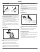
SAFETY DANGER Safety Understanding The Machine Safety Labels Safety-Alert Symbol The machine safety labels shown in this section are placed in important areas on your machine to draw attention to potential safety hazards. M131739, MX15340 On your machine safety labels, the words DANGER, WARNING, and CAUTION are used with this safety-alert symbol. DANGER identifies the most serious hazards. To avoid injury from rotating blades, stay clear of deck edge.
SAFETY DANGER WARNING MX15340, TCU15907 M131748, MX15340 To avoid injury from rotating blades and thrown objects, stay clear of deck edge and keep others away. Do not mow without discharge chute or entire grass catcher in place. To avoid injury from tipover, drive across slopes, not up and down. If machine stops going uphill, stop blades and back down slowly.
SAFETY WARNING Emission Control System Certification Label NOTE: Tampering with emission controls and components by unauthorized personnel may result in severe fines or penalties. Emission controls and components can only be adjusted by EPA and/or CARB authorized service centers. Contact your Great Dane Equipment Retailer concerning emission controls and component questions.
SAFETY Operator Training Required • The owner of the machine is responsible for training the users and mechanics of the machine. • The owner/user can prevent and is responsible for accidents or injuries occurring to themselves, other people, or property. • Do not allow operation or service of the machine by untrained adults. • Do not let children operate the machine. Local regulations may restrict the age of the operator. • Do not change the engine governor settings or overspeed the engine.
SAFETY Using a Spark Arrestor The engine in this machine is not equipped with a spark arrestor muffler. It is a violation of California Public Resource Code Section 4442 to use or operate this engine on or near any forest-covered, brush-covered or grasscovered land unless the exhaust system is equipped with a spark arrestor meeting any applicable local or state laws. Other states or federal areas may have similar laws. 7. Wait for engine and all moving parts to stop before you leave the operator’s seat. 8.
SAFETY PROTECT CHILDREN: • Transport machine with decks lowered to improve stability. • Drive machine very slowly and avoid quick stops when attachment is removed. • Drive across a hill, not up and down. Be careful when you change direction on a slope. If necessary, turn slowly and in the downhill direction. • Mowing when grass is wet can cause reduced traction and sliding. Keep Riders Off • Never assume that children will remain where you last saw them.
SAFETY Wear Appropriate Clothing Practice Safe Maintenance MIF MIF • Always wear safety goggles, or safety glasses with side shields, and a hard hat when operating the machine. • Only qualified, trained adults should service this machine. • Wear close fitting clothing and safety equipment appropriate for the job. • Understand service procedure before doing work. Keep area clean and dry. • While mowing, always wear substantial footwear and long trousers.
SAFETY • Charge batteries in an open, well-ventilated area, away from sparks. Unplug battery charger before connecting or disconnecting from the battery. Wear protective clothing and use insulated tools. Prevent Fires • Do not modify machine or safety devices. Unauthorized modifications may impair its function and safety.
SAFETY • When inflating tires, use a clip-on chuck and extension hose long enough to allow you to stand to one side and NOT in front of or over the tire assembly. • Check tires for low pressure, cuts, bubbles, damaged rims or missing lug bolts and nuts. Handling Fuel Safely Fuel and fuel vapors are highly flammable: • Static electric discharge can ignite gasoline vapors in an ungrounded fuel container.
OPERATING Operating Daily Operating Checklist ❏ Make sure all necessary guards and shields are safely and securely attached. Check for loose, missing, or damaged parts. H I J K - Throttle Lever - Mower Deck Lift/Lower Lever - Height-of-Cut (HOC) Adjustment Pin - Mower Deck Transport Position Lock Lever ❏ Remove mower deck belt shields. Clean grass and Miscellaneous Controls debris from belt area. ❏ Remove grass and debris from machine and mower deck. ❏ Test park brake. ❏ Test safety systems.
OPERATING The safety systems installed on your machine should be checked before each machine use. Be sure you have read the machine operator manual and are completely familiar with the operation of the machine before performing these safety system checks. Use the following checkout procedures to check for normal operation of machine. If there is a malfunction during one of these procedures, do not operate machine. See your authorized dealer for service. Perform these tests in a clear open area.
OPERATING Mounting and Dismounting Machine Safely Lowering the Seat: 1. Stand on the side of the machine. 2. Push operator seat back and slowly lower seat frame. A Adjusting Seat Front-to-Back Adjustment 1. Sit on the operator seat. MX15340 Do not step on the mower deck when mounting and dismounting the machine. Mount the machine from the front using the foot plate (A). Park machine safely (see Parking Safely in the Safety section) before dismounting. B A MX15280 Keep the foot plate clean.
OPERATING 2. Adjust mower deck to desired cutting height. A NOTE: The rear anti-scalp wheels are located under the rear of the mower deck. B D C MX13149 B A 2. Move the mower deck lift lever (A) to the transport position (D). 3. Position the HOC adjustment pin (C) in the proper hole for the desired height-of-cut. 4. Pull back and hold the mower deck lift lever (A) and release the transport position lock lever (B). A C MX15281 3. Adjust anti-scalp wheel (A) to one of two positions (B).
OPERATING Using the Key Switch NOTE: Machine will only start if the following conditions exist: A • Park brake is locked. • PTO is disengaged. • Motion control levers are in the neutral detent position (standard levers) or neutral lock position (optional “over the lap” levers). A MX15275 • Raise and pull rearward park brake lever (A) to the lock park brake. B STOP Unlocking Park Brake: C MIF A • To turn ignition off, turn key to the STOP position (A).
OPERATING Using the Throttle Lever Using the Choke (Carbureted Engines Only) Engage Choke: A B A C D MX15284 • Push throttle lever (A) all the way forward to the fullthrottle detent position (B) when mowing. • Move throttle lever (A) to the 1/2-throttle position (C) when starting and warming the engine. • Pull throttle lever (A) rearward to the slow position (D) to idle engine. Do not run engine at slow idle any longer than necessary. MX15284 • Pull choke knob (A) out.
OPERATING Neutral Position - Optional “Over the Lap” Levers Neutral Detent Position - Standard “Center Steer” Levers NOTE: When the control levers are in the neutral detent position, the control lever rollers (A) located on each side of the control console will be seated in the notches in the console. A MX15293 Picture Note: Motion control levers (A) shown in the neutral position.
OPERATING Forward: Gentle Right Turn: MX13114 MX13117 • Push both motion control levers forward at the same time. • Push left control lever farther forward than the right control lever. Reverse: Sharp Left Turn: MX13115 MX13118 • Pull both control levers past center rearward at the same time. Gentle Left Turn: • Push right control lever forward and pull left control lever rearward at the same time. Sharp Right Turn: MX13116 • Push right control lever farther forward than the left control lever.
OPERATING Starting the Engine c CAUTION: Avoid injury! Engine exhaust fumes contain carbon monoxide and can cause serious illness or death. IMPORTANT: Avoid damage! Starter may be damaged if starter is operated for more than 20 seconds at a time: • Wait 2 minutes before trying again if the engine does not start. Move the vehicle to an outside area before running the engine. Do not run an engine in an enclosed area without adequate ventilation.
OPERATING Engaging Mower Stopping the Engine c CAUTION: Avoid injury! Clear mowing area of all bystanders when operating this machine. Thrown objects could cause serious injury or death. Keep hands and feet away from blades and discharge opening. Do not mow in reverse unless absolutely necessary. IMPORTANT: Avoid damage! To help prevent engine backfiring, throttle lever should be set at the 1/4throttle position and run for 30 seconds prior to stopping the engine.
OPERATING clockwise (closed position). Tighten valve to 9-14 N•m (80120 lb-in.). Using Hydraulic Pump Free-Wheel Valves c CAUTION: Avoid injury! With the free-wheel valves open, the machine will have 6. Lock the park brake. Transporting Machine unrestricted motion. • The machine may free-wheel out of control if the free-wheel valves are opened with the machine on an incline.
OPERATING Mowing Travel Speeds Use slow travel speed for: • Trimming. • Working in close quarters. • Mowing tall grass. Use faster travel speeds for: • Normal mowing on level ground. Dismounting to Inspect Mower c CAUTION: Avoid injury! Help prevent serious injury. Keep hands and feet away from blades and the discharge opening. Do not step on either side of the mower deck when mounting and dismounting the machine. Mount and dismount the machine using the front foot plate. 1.
REPLACEMENT PARTS Replacement Parts Parts We recommend Great Dane quality parts available at your Great Dane dealer. Part numbers may change. Use part numbers listed below when you order. If a number changes, your dealer will have the latest number. When you order parts, your Great Dane dealer needs your machine model and serial numbers and engine serial number. These are the numbers that you recorded in the Product Identification section of this manual.
SERVICE INTERVALS Remove debris from the underside of the mower deck. Service Intervals Servicing Your Machine IMPORTANT: Avoid damage! Operating in extreme conditions may require more frequent service intervals: Every 50 Hours or Weekly (Whichever Comes First) • Engine components may become dirty or plugged when operating in extreme heat, dust or other severe conditions. Change engine oil and filter. See the engine manufacturer’s owner’s manual provided with your machine for the complete procedure.
SERVICE LUBRICATION Service Lubrication Grease IMPORTANT: Avoid damage! If operating outside that temperature range, contact your servicing dealer for a special-use grease. D Use a general all-purpose grease with an NLGI grade No. 2 rating. Wet or high-speed conditions may require use of a specialuse grease. Contact your servicing dealer for information. Spray Lubricant MX15319 Use a general-purpose petroleum-based spray lubricant.
SERVICE LUBRICATION NOTE: Use spray lubricant to lubricate the following items: K L H M MX15288 • 48-, 51- and 61-Inch Mower Deck: Grease mower deck drive belt tension arm (H). MX15335 Picture Note: 48-, 52- and 61-inch mower decks. J K I L M MX15331 MX15331 • Picture Note: 72-inch mower deck. 72-Inch Mower Deck: • Grease engine-to-deck drive belt tension arm (I). • Lubricate mower deck idler pulleys (K-M). • Apply spray lubricant to the spindle drive belt tension arm (J).
SERVICE ENGINE Service Engine Engine Warranty Maintenance Statement Maintenance, repair, or replacement of the emission control devices and systems on this engine, which are being done at the customer’s expense, may be performed by any nonroad engine repair establishment or individual. Warranty repairs must be performed by an authorized Great Dane servicing dealer. 1. Park machine safely. (See Parking Safely in the Safety section.) 2. Allow engine to cool. 3.
SERVICE ENGINE MODEL Oil Capacity With Filter (Dry) Kawasaki Engines 1.8 L (1.9 qt) Kohler Engines 2.0 L (2.1 qt) Checking and Cleaning Air Filter Elements A MX15321 3. Put container under drain tube. c CAUTION: Avoid injury! Touching hot surfaces can burn skin. The engine and components will be hot if the engine has been running. Allow the engine to cool before servicing. 4. Open drain valve (A) using a 10 mm socket, 1 ft extension, swivel and 3/8 in. drive ratchet. 5.
SERVICE ENGINE Checking Spark Plug c CAUTION: Avoid injury! Touching hot surfaces can burn skin. The engine and components will B be hot if the engine has been running. Allow the engine to cool before servicing. Check spark plugs at the intervals recommended in the Service Intervals section. See the engine manufacturer’s owner’s manual provided with your machine for the complete procedure. A C MX15300 Adjusting Carburetor - Carbureted Engines Picture Note: Kawasaki engine shown. 4.
SERVICE ENGINE c CAUTION: Avoid injury! Fuel system under pressure. Wear personal eye protection when Troubleshooting the Kohler Electronic Fuel Injection System disconnecting fuel hoses to guard against spraying fuel. B C A A MX15301 4. Disconnect fuel hose (A) from the outlet side of fuel filter (B), and drain gasoline into a properly marked container. MX15334 5. Remove fuel filter from inlet fuel hose (C). Discard filter.
SERVICE ENGINE Keep in mind that EFI-related problems are more often caused by the wiring harness or connections than by the EFI components. Even small amounts of corrosion or oxidation on the terminals can interfere with the milliampere currents used in system operation. Cleaning the connectors and grounds will solve problems in many cases. In an emergency situation, simply disconnecting and reconnecting the connectors may clean up the contacts enough to restore operation, at least temporarily.
SERVICE TRANSMISSION Service Transmission Hydraulic Oil A Use only 5W-50 or 15W-50 all synthetic oil. Checking Hydraulic Oil Level IMPORTANT: Avoid damage! Check oil level in reservoir tank when oil is cold. Do not overfill oil reservoir tank. Oil will expand during operation and could overflow. 1. Park machine safely. (See Parking Safely in the Safety section.) MX15294 4. Remove cap (A) from oil reservoir tank filler neck. A B MX15294 MX15312 2.
SERVICE TRANSMISSION c CAUTION: Avoid injury! Engine exhaust fumes contain carbon monoxide and can cause serious illness or death. Move the machine to an outside area before running the engine. Do not run an engine in an enclosed area without adequate ventilation. • Connect a pipe extension to the engine exhaust pipe to direct the exhaust fumes out of the area. • Allow fresh outside air into the work area to clear the exhaust fumes out. A MX13120 2.
SERVICE TRANSMISSION 5. Install new drive belt. 6. Install mower deck drive belt as shown. A Checking and Adjusting Motion Control Linkages B c CAUTION: Avoid injury! Do not attempt this adjustment unless you are a qualified and properly trained technician. MX15350 Check Neutral Creep c CAUTION: Avoid injury! Engine exhaust fumes can cause sickness or death: • If it is necessary to run an engine in an enclosed area, use an exhaust pipe extension to remove the fumes.
SERVICE TRANSMISSION 2. Sit on the seat, and start the engine. 3. Operate machine to bring the hydraulic oil to normal operating temperature. 4. Move the machine in a level, wide-open area, such as an empty parking lot. 5. Run the engine at full throttle. 6. Move and hold both control levers to the full forward position. Observe the machine travel. If the machine does not travel in a straight line, adjustment is required. Note the direction the machine moves. Maximum Speed Drift Adjustment 1.
SERVICE TRANSMISSION Hydraulic System Hose Routing A B C F D E MX15332 A B C D E F - Hydraulic Reservoir - Oil Filter - Right Hydraulic Pump - Right Wheel Motor - Left Wheel Motor - Left Hydraulic Pump Service Transmission - 35
SERVICE TRANSMISSION Hydraulic System Schematic E G D B C F A H I D D B C A H F D I J K L M MX15333 A B C D E F G - Control Input Shaft - Pump Block - Charge Pump - Charge System Check Valve - Right Hydraulic Pump - Manual Bypass (Free-Wheel) Valve - Right Wheel Motor H I J K L M - Cooling Orifice - Charge Relief Valve - Left Wheel Motor - Left Hydraulic Pump - Oil Filter - Hydraulic Reservoir Service Transmission - 36
SERVICE STEERING & BRAKES Service Steering & Brakes Remove and Install Front Caster Wheels A Removing 1. Park machine safely. (See Parking Safely in the Safety section.) 2. Lift front of machine with a safe lifting device. B C E B F D E A C MX15324 3. Remove locknut (A), capscrew (B), two trash guards (C) and wheel and tire assembly (D). 4. Remove bearings (E) and spacer tube (F) from wheel. C MX15323 5. Wipe clean and inspect bearings (E). Replace bearings as needed. 6.
SERVICE STEERING & BRAKES A A B D E MX15286 F 2. Remove dust cover (A) from top of spindle. B C C F D E MX15339 3. Remove locknut (A), capscrew (B) and wheel assembly (C). 4. Remove spacers (D), seals (E) and bearings and bearing races (F) from wheel. 5. Clean and inspect bearings (F) and pack with clean grease. Replace bearings with races as needed. MX15316 6. Install bearings and races (F) and new seals (E). 7. Install wheel assembly (C), two spacers (D), capscrew (B) and locknut (A).
SERVICE STEERING & BRAKES 2. The control lever gap is pre-set at the factory. If the gap requires adjustment, see your authorized Great Dane servicing dealer. A B C Height Adjustment Procedure J The position of the control levers can be varied higher or lower by approximately 25 mm (1 in.) depending on the holes chosen for mounting the lever. F L G I H C E D MX15352 • To mount in the high position, mount the levers to the top four holes in the mounting bracket. MX15325 3.
SERVICE STEERING & BRAKES NOTE: If the ends of the levers strike against each other while in the neutral position, move the levers to the neutral lock position and carefully bend them outward. Move them back to the neutral position and check for the recommended gap of 3-6 mm (1/8-1/4 in.). A B • If positions of the control levers are unequal, an adjustment is necessary. Alignment Procedure 1. Adjust position of motion control levers: MX13130 2. Loosen set screw (A). 3.
SERVICE MOWER Service Mower Removing and Installing Mower Deck Foot Plate c CAUTION: Avoid injury! Help prevent serious personal injury. Do not operate the mower Removing and Installing Mower Deck Belt Shields c CAUTION: Avoid injury! Help prevent serious personal injury. Do not operate the mower without the belt shields installed. without the foot plate installed. Removing Foot Plate Removing Belt Shields 1. Park machine safely. (See Parking Safely in the Safety section.) 1. Park machine safely.
SERVICE MOWER Leveling Mower Deck 4. Measure from outside blade tip to the ground. c CAUTION: Avoid injury! Rotating blades are dangerous. Before adjusting or servicing mower: • Disconnect spark plug wire(s) to prevent engine from starting accidently. • The difference between both measurements should be no greater than 3 mm (1/8 in.). 5. If side-to-side level is not within specifications, an adjustment is necessary.
SERVICE MOWER Adjusting Level (Front-to-Rear) IMPORTANT: Avoid damage! Adjust the left and right deck lift assist rods equally. C NOTE: Adjust side-to-side mower level before adjusting front-to-rear level. Chariot LX model is equipped with a deck lift assist rod on each side of machine. Adjust both sides of the mower deck equally. A B F E MX15342 D 2. Check clearance (A) from the top of the thrust arms (B) to the bottom of the thrust arm stop rod (C). The clearance should be 3 mm (1/8 in.).
SERVICE MOWER Adjusting Deck Lift Assist Spring Tension NOTE: Deck lift assist spring tension is adjusted at the factory. If the effort required to raise or lower the mower deck is not satisfactory, an adjustment may be necessary. Checking and Adjusting Mower Deck Drive Belt Tension - 48-, 52- and 61-Inch Mower Deck 1. Park machine safely. (See Parking Safely in the Safety section.) 2. Adjust the mower deck for the lowest cutting height, and lower the deck. Check Spring Tension 1.
SERVICE MOWER • To increase belt tension: Turn nut (B) clockwise. • To decrease belt tension: Turn nut (B) counterclockwise. Removing and Installing Mower Deck Drive Belt - 48-, 52- and 61-Inch Mower Deck 1. Park machine safely. (See Parking Safely in the Safety section.) A 2. Raise foot platform. MX15328 3. Remove mower deck drive belt covers. 4. Check the engine-to-deck drive belt tension. The belt should deflect a maximum of 13 mm (1/2 in.) when a force of 4.
SERVICE MOWER A B C A H MX15328 D G 3. Release engine-to-deck drive belt tension by turning the tension adjuster nut (A) counterclockwise. F A E MX15318 A B C D E F G H - PTO Clutch Sheave - Mower Deck Drive Belt - Tension Idler Sheave - Left Spindle Sheave - Center Spindle Sheave - Idler Sheave - Right Spindle Sheave - Idler Sheave B C 6. Install new mower deck drive belt (B) as shown. E 7. Adjust belt tension. D 8. Install mower deck drive belt covers. MX15329 9. Lower foot platform.
SERVICE MOWER Removing and Installing Spindle Drive Belt 72-Inch Mower Deck 1. Park machine safely. (See Parking Safely in the Safety section.) Checking and Replacing Mower Blades c CAUTION: Avoid injury! Help prevent serious personal injury. Do not work near a raised 2. Raise foot platform. mower deck unless it is safely supported. 3. Remove mower deck drive belt covers. Never start the engine or engage the PTO switch when performing this service procedure.
SERVICE MOWER Replacing Mower Blades A A B C D MX8333 • Keep original bevel (A) when grinding. • Blade should have 0.40 mm (1/64 in.) cutting edge (B) or less. B • Balance blades before installing. MX15357 1. Use two long-handled 15/16 in. wrenches to loosen nut (A). 2. Remove nut (A), blade bolt (B), three 1/4 in. washers (C) and blade (D). 3. Install replacement blade: • Balancing Blades c CAUTION: Avoid injury! Mower blades are sharp.
SERVICE MOWER 2. Remove mower blade. (See Checking and Replacing Mower Blades.) 12.Install mower blade, blade washers and blade bolt assembly. Tighten nut to 81 N•m (60 lb-ft). (See Checking and Replacing Mower Blades.) A Replacing Mower Spindle Bearings - 72-Inch Mower Deck B 1. Park machine safely. (See Parking Safely in the Safety section.) 2. Remove engine-to-deck drive and spindle drive belts. C 3. Remove mower blade. (See Checking and Replacing Mower Blades.
SERVICE MOWER 5. Remove retaining ring (I), spindle shaft (J), lower bearing (K) and spacer (L) from spindle housing (M). Discard bearing. 6. Remove and discard upper bearing (N). 7. Clean entire assembly. 8. Install a new lower bearing (K) and spacer (L) on the spindle shaft (J). IMPORTANT: Avoid damage! The clearance between the lower bearing and the housing is only 0.05 mm (0.002 in.). Do not force bearing into housing. 9.
SERVICE ELECTRICAL Installing: Service Electrical WARNING: Battery posts, terminals and related accessories contain lead and lead components, chemicals known to the State of California to cause cancer and reproductive harm. Wash hands after handling. 1. Install battery (H) using J-bolts (G), bracket (F), washers and nuts (E). 2. Connect the positive battery cable (D) first, then the negative cable (B). 3. Apply petroleum jelly or silicone spray to the terminals to prevent corrosion.
SERVICE ELECTRICAL Using Booster Battery 3. Connect negative booster cable to booster battery negative post (E). 4. Connect the other end (F) of negative booster cable to a unpainted metal part of the disabled machine’s engine, away from battery. 5. Start the engine of the disabled machine and run machine for several minutes. 6. Carefully disconnect the booster cables in the exact reverse order: negative cable first and then the positive cable.
SERVICE ELECTRICAL B C A MX15337 Chariot LX models equipped with Kohler EFI engines have three additional fuses: • One 10-amp fuse (A), used to protect the fuel pump circuit. • One 20-amp fuse (B), used to protect the main power circuit. • One 30-amp fuse (C), used to protect the charge circuit. 1. Remove defective fuse from socket. 2. Check metal clip in fuse window and discard fuse if clip is broken. 3. Install new fuse into socket.
SERVICE ELECTRICAL Wiring Schematic - Carbureted Engines MX15338 Service Electrical - 54
SERVICE ELECTRICAL Wiring Schematic - 26 HP Fuel Injected Engine MX15345 Service Electrical - 55
SERVICE ELECTRICAL Wiring Schematic - 28 HP Fuel Injected Engine MX15356 Service Electrical - 56
SERVICE MISCELLANEOUS Checking Tire Pressure Service Miscellaneous Filling Fuel Tank Use regular grade 87 octane unleaded fuel. (For gasoline engines only.) c CAUTION: Avoid injury! Fuel vapors are explosive and flammable: • Shut engine off before filling fuel tank. • Do not smoke while handling fuel. • Keep fuel away from flames or sparks. • Fill fuel tank outdoors or in well ventilated area. • Clean up spilled fuel immediately.
SERVICE MISCELLANEOUS Remove and Install Rear Drive Wheels Cleaning and Repairing Metal Surfaces Removing: Cleaning: 1. Park machine safely. (See Parking Safely in the Safety section.) Follow automotive practices to care for your machine’s painted metal surfaces. Use a high-quality automotive wax regularly to maintain the factory look of your machine’s painted surfaces. Repairing Minor Scratches (Surface Scratch): 1. Clean area to be repaired thoroughly.
TROUBLESHOOTING Troubleshooting Using Troubleshooting Chart If you are experiencing a problem that is not listed in this chart, see your Great Dane servicing dealer for service. When you have checked all the possible causes listed and you are still experiencing the problem, see your Great Dane servicing dealer. Engine If Check Engine Will Not Start or Is Hard to Start Motion control levers not in the neutral detent (or neutral lock) position. Park brake lever unlocked.
TROUBLESHOOTING If Check Engine Runs Rough or Stalls Plugged fuel filter. Plugged air intake system. Fuel cap vent dirty. Stale or improper fuel/fuel level. Spark plug not gapped correctly. Replace spark plug. Carbureted Engines Only: Choke adjusted incorrectly. See your Great Dane servicing dealer. EFI system problem - check EFI electrical system and connections. If problem continues, have system serviced by an authorized Kohler EFI servicing dealer. Engine Knocks Engine oil level low. Reduce load.
TROUBLESHOOTING If Check Engine Backfires Through Muffler Throttle should be at low idle for several seconds before turning off machine. Leaking/damaged exhaust manifold gasket. EFI system problem - check EFI electrical system and connections. If problem continues, have system serviced by an authorized Kohler EFI servicing dealer. High Fuel Consumption Improper type of fuel. Plugged air intake system. Operating at too fast ground speed for conditions. Improper valve clearance.
TROUBLESHOOTING If Check Starter Turns Slowly Loose or corroded battery or ground connections. Low battery power - charge battery. Engine oil viscosity too heavy. Hydraulic pump linkages failed and are engaged. Machine If Check Excessive Machine Vibration Engine speed too slow. Machine Will Not Move With Engine Running Park brake locked. Transmission hydraulic oil level low. Transmission oil cold - allow engine to warm. Traction drive belt slipping. Hydraulic pump free-wheel valves open.
TROUBLESHOOTING If Check Machine Moves to the Left or Right With Engine Running and Transmission in Neutral Pump linkage (neutral position) out of adjustment. Mower Deck If Check Discharge Chute Plugged Grass is wet - mow grass only when dry. Raise cutting height. Mow at full throttle. Ground speed too fast for conditions. Correct installation of deck drive belt. Mower Deck Vibrates Run engine at full throttle. Loose hardware. Check/replace mower deck drive belt.
STORAGE Engine: Storage Storing Safety Engine storage procedure should be used when vehicle is not to be used for longer than 60 days. c CAUTION: Avoid injury! Fuel vapors are explosive and flammable. Engine exhaust 1. Change engine oil and filter while engine is warm. fumes contain carbon monoxide and can cause serious illness or death: 2. Service air filter if necessary. • Run the engine only long enough to move the machine to or from storage. 4. Remove spark plugs. Put 30 mL (1 oz.
ASSEMBLY 7. Install cap on filler neck. Assembly Bag of Parts Qty. Description 1 Key 1 Operator’s Manual 1 PDR Check List Check Engine Oil Level Remove dipstick from tube by unscrewing it. Wipe it clean. 8. Install dipstick and allow the cap to rest on the end of the tube. Do not tighten the cap. 9. Remove dipstick. Check oil level on dipstick; oil level should be between the ADD and FULL marks. • If oil is low, add oil to bring oil level no higher than the FULL mark on dipstick.
ASSEMBLY Install Motion Control Levers B A D A C C MX15344 2. Pivot seat frame (A) forward until it rests on the hinge stops. NOTE: The seat mounting hardware is attached to the seat plate with tie straps. MX15343 1. Remove hardware from control arms. 3. Install seat (B) to the seat frame, using four 5/16-18 locknuts and heavy flat washers (C). Tighten locknuts to 27 N•m (20 lb-ft). NOTE: The control lever mounting brackets have six holes.
ASSEMBLY Initial Adjustments c CAUTION: Avoid injury! Clear area of bystanders before performing this service procedure. 1. Check free-wheel valves on both pump assemblies to make sure that the valves are closed. Tighten valves to 108-163 N•m (80-120 lb-ft). 2. Raise the rear of the machine until the drive wheels are off the ground. Support the machine with jackstands. c CAUTION: Avoid injury! Engine exhaust fumes contain carbon monoxide and can cause serious illness or death.
SPECIFICATIONS Specifications Engine NOTE: See engine manufacturer’s owner’s manual provided with your machine for engine specifications. Net Weight - Chariot LX (With Mower Deck and Without Fuel) 25-hp Kawasaki Engine/61-in. Deck . . . . 501 kg (1104 lb) 25-hp Kohler Engine/61-in. Deck . . . . . . . 501 kg (1104 lb) Battery 26-hp Kohler Engine/61-in. Deck . . . . . . . 501 kg (1104 lb) Voltage . . . . . . . . . . . . . . . . . . . . . . . . . . . . . . . . . . . 12 volt 27-hp Kohler Engine/61-in.
SPECIFICATIONS Height Adjustment Increments . . . . . . . . . . 13 mm (1/2 in.) 52-Inch Mower Deck Mower Type . . . . . . . . . . . . .Mulch, Bag or Side Discharge Cutting Blades . . . . . . . . . . . . . . . . . . . . . . . . . . . . . . . . . 3 Blade Bolt Torque . . . . . . . . . . . . . . . . . . 81 N•m (60 lb-ft) Cutting Width . . . . . . . . . . . . . . . . . . . . . . . . 1.32 m (52 in.) Cutting Height (approximate) . . . 25 to 127 mm (1 to 5 in.) Height Adjustment Increments . . . . . . . . . .
INDEX Index A Air Cleaner Elements, Checking and Cleaning .............. 27 Assembly ........................................................................ 65 B Balancing Blades ............................................................ 48 Battery, Cleaning ............................................................ 51 Battery, Remove and Install ........................................... 51 Battery, Specifications .................................................... 68 Battery, Using Booster ......
INDEX Mower Deck, Troubleshooting ........................................ 63 Mower, Dismounting to Inspect ...................................... 21 Mower, Engaging ........................................................... 19 Mowing Tips ................................................................... 20 Mowing Travel Speeds ................................................... 21 N Neutral Start Switch, Test ............................................... 11 O Oil Level, Checking Engine .............
SERVICE RECORD GD Service Record GD Record Service Dates Engine Oil and Filter Change Lubricate Machine Air Cleaner Element Clean/Replace Service Record GD - 72