Predelivery Manual 1205NT End-Wheel, No-Till Drill Manufacturing, Inc. ! Read the operator’s manual entirely. When you see this symbol, the subsequent instructions and warnings are serious - follow without exception. Your life and the lives of others depend on it! 14001 Cover illustration may show optional equipment not supplied with standard unit.
Table of Contents Important Safety Information . . . . . . . . . . . . . 1 Safety at All Times . . . . . . . . . . . . . . . . . . . 6 Description of Unit . . . . . . . . . . . . . . . . . . . 7 Intended Usage . . . . . . . . . . . . . . . . . . 7 Models Covered . . . . . . . . . . . . . . . . . . 7 Introduction . . . . . . . . . . . . . . . . . . . . . . . . . . . 7 Using This Manual . . . . . . . . . . . . . . . . . . . 8 Definitions . . . . . . . . . . . . . . . . . . . . . .
Important Safety Information 1 Important Safety Information Look for Safety Symbol The SAFETY ALERT SYMBOL indicates there is a potential hazard to personal safety involved and extra safety precaution must be taken. When you see this symbol, be alert and carefully read the message that follows it.
2 1205NT Be Familiar with Safety Decals ▲ Read and understand “Safety Decals,” page 4, thoroughly. ▲ Read all instructions noted on the decals. Keep Riders Off Machinery Riders obstruct the operator’s view. Riders could be struck by foreign objects or thrown from the machine. ▲ Never allow children to operate equipment. ▲ Keep all bystanders away from machine dur- ing operation. Shutdown and Storage ▲ Lower drill, put tractor in park, turn off engine, and remove the key.
Important Safety Information 3 Transport Machinery Safely Maximum transport speed for implement is 20 mph. Some rough terrains require a slower speed. Sudden braking can cause a towed load to swerve and upset. ▲ Do not exceed 20 mph. Never travel at a speed which does not allow adequate control of steering and stopping. Reduce speed if towed load is not equipped with brakes. ▲ Comply with state and local laws. ▲ Do not tow an implement that, when fully loaded, weighs more than 1.
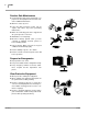
4 1205NT Practice Safe Maintenance ▲ Understand procedure before doing work. Use proper tools and equipment. Refer to this manual for additional information. ▲ Work in a clean, dry area. OFF ▲ Lower the drill, put tractor in park, turn off engine, and remove key before performing maintenance. ▲ Make sure all moving parts have stopped and all system pressure is relieved. ▲ Allow drill to cool completely.
Important Safety Information 5 Handle Chemicals Properly Agricultural chemicals can be dangerous. Improper use can seriously injure persons, animals, plants, soil and property. ▲ Read and follow chemical manufacturer’s instructions. ▲ Wear protective clothing. ▲ Handle all chemicals with care. ▲ Avoid inhaling smoke from any type of chemi- cal fire. ▲ Store or dispose of unused chemicals as specified by chemical manufacturer.
6 1205NT Safety at All Times Thoroughly read and understand the instructions in this manual before operation. Read all instructions noted on the safety decals. ▲ Be familiar with all drill functions. ▲ Operate machinery from the driver’s seat only. ▲ Do not leave drill unattended with tractor engine running. ▲ Do not dismount a moving tractor. Dismount- ing a moving tractor could cause serious injury or death. ▲ Do not stand between the tractor and drill dur- ing hitching.
Introduction 7 Introduction Great Plains Manufacturing wants you to be satisfied with any new machine delivered by the Great Plains Trucking network. To ease the assembly task and produce a properly working machine, read this entire manual before assembling or setting up new equipment. Description of Unit The 1205NT Drill is a 12' grain drill of end wheel design which couples Great Plains spring mounted coulter with a straight arm design of our solid stand opener to achieve no-till drilling capabilities.
8 1205NT Using This Manual This manual was written to help you assemble and prepare the new machine for the customer. The manual includes instructions for assembly and setup. Read this manual and follow the recommendations for safe, efficient and proper assembly and setup. An operator’s manual is also provided with the new machine. Read and understand “Important Safety Information” and “Operating Instructions” in the operator’s manual before assembling the machine.
Assembly 9 Assembly The following headings are step-by-step instructions for assembling the 1205NT Drill. Begin with “Tools Required” and “Pre-Assembly Checklist” to make sure you have all necessary parts and equipment. Follow each step to make the job as quick and safe as possible and produce a properly working machine. The 1205NT Drill is shipped via flat bed truck. It is the dealer’s responsibility to unload the new machine. Unload all equipment before beginning assembly.
10 1205NT 9. Check that all safety decals and reflectors are located correctly and legible. Replace if improperly located or damaged. Refer to “Safety Decals” in the operator’s manual. 10. Inflate tires to recommended pressure as listed on the “Tire Inflation Chart,” page 17. Tighten wheel bolts as specified on “Torque Values Chart,” page 16. Tongue Assembly See Figure 1.
Assembly 11 Hydraulic Attachment NOTE: The SAE O-RING and JIC 37 (deg) flare type hose connections do not require sealant for reconnecting. They do not require high torque for a good seal. IMPORTANT: When using sealant on pipe threads the friction between the threads is reduced; therefore, be certain not to over tighten which may cause damage to a valve, cylinder port or fitting.
12 1205NT Setup Hitching Tractor to Drill ! DANGER You may be severely injured or killed by being crushed between the tractor and drill. Do not stand or place any part of your body between drill and moving tractor. Stop tractor engine and set park brake before installing the hitch pin. Hitch Assembly 1. See Figure 5. Insert upper hitch plate (1) into clevis hitch (2) with a spacer tube (3) on each side of ball swivel. 2. Bolt in place with 1 x 5 1/2 inch bolt (4), flat washer (5) and nylock nut (6).
Setup 13 Hitching to Tractor Refer to Figure 7. 1. Back tractor to drill. Using the screw jack, adjust drill tongue to get drawbar under upper hitch plate (1). 2. Align rear hole in upper hitch plate with large hole in drawbar. Place lower hitch plate (4) under drawbar and attach to upper hitch plate with two 5/8 x 4 inch bolts (5), flat washers (6) and nylock nuts (7). 3.
14 1205NT Hydraulic Hose Hookup Great Plains hydraulic hoses are color coded to help you hookup hoses to your tractor outlets. Hoses that go to the same remote valve are marked with the same color. Color Hydraulic Function Blue Transport Lift Cylinders Orange Marker Cylinders To distinguish hoses on the same hydraulic circuit, refer to plastic hose holder. Hose under extendedcylinder symbol feeds cylinder base ends. Hose under retracted-cylinder symbol feeds cylinder rod ends.
Setup 15 2. With drill attached to tractor, jack drill up and support frame at ends near gauge wheels. 3. With drill raised and supported, unpin cylinders from gauge wheel arms and frame. Turn cylinders "rod end up". Wire or otherwise safely support rod ends higher than base ends. NOTE: In order to prevent trapped air pockets, rod end must be higher than any other part of cylinder during bleeding operation. 4. With tractor engine idling, engage tractor hydraulics to extend cylinder rods.
16 1205NT Appendix Torque Values Chart for Common Bolt Sizes Bolt Head Identification Bolt Head Identification Bolt Size (Inches) in-tpi 1 Grade 2 2 Grade 5 3 Grade 8 Bolt Size (Metric) N·m ft-lb N·m ft-lb N·m ft-lb mm x pitch 1/4" - 20 7.4 5.6 11 8 16 12 M 5 X 0.8 4 5.8 8.8 10.9 Class 5.8 Class 8.8 Class 10.9 N·m ft-lb N·m ft-lb N·m ft-lb 4 3 6 5 9 7 1/4" - 28 8.5 6 13 10 18 14 M6X1 7 5 11 8 15 11 5/16 - 18 15 11 24 17 33 25 M 8 X 1.
Appendix 17 Tire Inflation Chart Tire Size 3/24/06 Inflation PSI Tire Size Inflation PSI 7.50 x 20" 4-Ply Drill Rib 28 11L x 15" 6-Ply Rib Implement 28 9.0 x 22.5 10-Ply Highway Service 70 70 11L x 15" 12-Ply Rib Implement 52 9.0 x 24" 8-Ply Rib Implement 40 12.5L x 15" 8-Ply Rib Implement 36 9.5L x 15" 6-Ply Rib Implement 32 12.5L x 15" 10-Ply Rib Implement 44 9.5L x 15" 8-Ply Rib Implement 44 16.5L x 16.1" 10-Ply Rib Implement 36 9.
Great Plains Manufacturing, Inc. Corporate Office: PO.