--1 4/8/04 Operator’s/Parts Manual 30’ 3-Section Flat Fold Marker Manufacturing, Inc. P.O. Box 5060 ● Salina, Kansas 67402-5060 ! © Copyright 1996 Printed 7/30/96 113-368M Read the Operator’s manual entirely. When you see this symbol, the subsequent instructions and warnings are serious - follow without exception.
4/8/04 INTRODUCTION 1-0 Your Great Plains 30’ 3-Section Drill Flat Fold Marker is designed to give you many years of dependable service. This manual has been prepared to instruct you in the safe and efficient operation of this machine. Read and study it thoroughly. Follow all instructions and service procedures carefully. The parts on your 30’ 3-Section Drill Flat Fold Marker have been specially designed and should only be replaced with genuine Great Plains parts.
1-1 4/8/04 TABLE OF CONTENTS Introduction -------------------------------------------------------------- 1-0 Table Of Contents ----------------------------------------------------- 1-1 Nut & Bolt Torquing Chart ------------------------------------------- 1-2 Safety Rules ------------------------------------------------------------- 1-2 Flat Fold Marker Field Installation Diagram---------------------- 1-3 Installation Instructions------------------------------------------------ 1-4 Single Flat Fold Marker
NUT & BOLT TORQUING CHART 4/8/04 1-2 This chart is based on torque requirements in foot pounds for grade 5 bolts. BOLT DIAMETER 1/4" 5/16" 3/8" 7/16" 1/2" 9/16" 5/8" MINIMUM TORQUE 9 17 35 54 80 110 150 MAXIMUM TORQUE 11 20 42 64 96 132 180 BOLT DIAMETER MINIMUM TORQUE 3/4" 7/8" 1" 1 1/8" 1 1/4" 1 3/8" 1 1/2" MAXIMUM TORQUE 270 400 580 800 1120 1460 1940 324 480 696 880 1240 1680 2200 NOTE: Torque requirements listed above do not apply to self-locking nuts.
1-3 11009 113-368M FLAT FOLD MARKER FIELD INSTALLATION DIAGRAM 4/8/04
4/8/04 INSTALLATION INSTRUCTIONS FLAT FOLD MARKER 1-4 FOR THE FOLLOWING ASSEMBLY INSTRUCTIONS, REFER TO THE ILLUSTRATION ON PAGE1-3. See the "Parts Section" of this manual to identify individual components not mentioned in these installation instructions. 1. Place drill in a lowered field position. From each end of the drill box allow 16 ft. clearance for marker assembly. 2. Attach the marker first section with mount (#1) to the marker mounting on the drill frame as illustrated.
SINGLE FLAT FOLD MARKER HYDRAULIC ASSEMBLY INSTRUCTIONS 1-5 4/8/04 10060 Fig. 1 Refer to Fig. 1 as reference for the following instructions: 1. Attach fittings (#1) & (#2) to cylinder ports. 2. Attach the needle valve (#3) and hoses to the cylinder fittings. 3. Bolt selector valve (#4) to the selector valve mount on T-Frame with 3/8" x 3" long bolts (#5), flat washers (#6) lock washer (#7) and nut (#8). 4.
4/8/04 DUAL FLAT FOLD MARKER ASSEMBLY INSTRUCTIONS 1-6 10059 Fig. 2 Refer to Fig. 2 as reference for the following instructions: 1. Attach the hydraulic fittings (#12) to the marker cylinder. 2. Install the selector/sequence valve to the selector valve mount, located on the T-Frame, using 3/ 8" bolts (#2), flat washers (#3), lock washers (#4), and hex nuts (#5). 3. Route hoses (#6) from the selector/sequence valve down the transport frame tube.
BLEEDING OF THE HYDRAULICS 1-7 4/8/04 1. Be sure tractor hydraulic reservoir is full. 2. With the marker(s) in field position, crack the hydraulic hose fitting(s) located at the base end of the cylinder(s). With your tractor at an idle speed, activate your tractor hydraulic valve until hydraulic oil seeps out around the hose ends. Tighten the hose end fittings and repeat this process with the hose end fitting(s) located at the rod end of the cylinder(s).
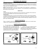
MAINTENANCE AND LUBRICATION 4/8/04 1-8 BREAKAWAY PROTECTION The marker arm (#2) is attached to the marker body (#1) with a 3/8" shear bolt. If excessive force is put on the marker during operation, the shear bolt will break, allowing the marker arm to swing away rather than cause damage to the marker. NOTE: The breakaway bolt is a 3/8"-16 x 2" long - grade 2 (G.P. # 802-266C). It is identified as a grade 2 by having no marks on the head.
1-9 TROUBLE SHOOTING 4/8/04 PROBLEM SOLUTION Hydraulic marker functioning improperly a. Check all hose fittings and connections for air and oil leaks. b. The chain on the folding marker should be slack when the marker is both fully extended and fully raised. c. Check tractor hydraulic oil level. d. Check all bolts and fasteners. e. If needle valve is plugged; open valve, cycle markers, and reset the needle valve. f. Double selector valve positioned for fold cylinders.
4/8/04 1-10 WARRANTY Great Plains Manufacturing, Incorporated warrants to the original purchaser that this seeding equipment will be free from defects in material and workmanship for a period of one year from the date of original purchase when used as intended and under normal service and conditions for personal use; 90 days for commercial or rental purposes.
1-11 113-368M NOTES 4/8/04
4/8/04 1-12 4/13/93 30' 3-SECTION DRILL FLAT FOLD MARKERS TABLE OF CONTENTS Flat Fold Marker------------------------------------------------------- 1-13 Marker Disk Assembly ---------------------------------------------- 1-15 Single Flat Fold Marker Hydraulic Assembly ------------------ 1-17 Dual Marker Hydraulic Assembly --------------------------------- 1-19 Cylinder {810-118C} and {810-019C} --------------------------- 1-21 Double Selector Valve (810-023C) ------------------------------- 1-23 Selecto
1-13 10106 113-368M FLAT FOLD MARKER 4/8/04
FLAT FOLD MARKER (CON’T) 4/8/04 Ref. Part No. 1. 2. 3. 4.
1-15 11485 113-368M MARKER DISK ASSEMBLY 4/8/04
MARKER DISK ASSEMBLY (CON’T) 4/8/04 Ref. Part No. 1. 2. 3. 4. 5. 6. 7. 8. 9. 10. 11. 12. 802-240C 890-213C 805-045C 803-185C 820-098C 113-369H 804-021C 822-045C 822-050C 815-039C 816-135C 113-562H 113-363H 815-038C 113-563S 113-364S 13. 14. 1-16 Description HHCS 1/2-20X1 GR5 GREASE CAP 1.785 X .89 PIN COTTER 5/32 X 1 1/4 LG NUT HEX SLOTTED 5/8-18 PLT 14 4-BOLT MARKER DISK DEPTH BAND 10 4-BOLT 4B.C. WASHER FLAT 5/8 SAE PLT BEARING CONE #LM 11949 BEARING CUP #LM 11949 HUB MACH 4 4 BOLT 2.
1-17 10217 113-368M SINGLE FLAT FOLD MARKER HYDRAULIC ASSEMBLY 4/8/04
SINGLE FLAT FOLD MARKER HYDRAULIC ASSEMBLY (CON'T.) 4/8/04 Ref. Part No. 1. 2. 3. 4. 5. 6. 7. 8. 9. 10. 11. 12. 13. 14. 15. 16. 17. 18. 19. 20. 21. 22. 23. 24. 25.
1-19 10212 113-368M DUAL FLAT FOLD MARKER HYDRAULICS ASSEMBLY 4/8/04
DUAL FLAT FOLD MARKER HYDRAULICS ASSEMBLY (CON'T.) 4/8/04 Ref. Part No. 1. 2. 3. 4. 5. 6. 7. 8. 9. 10. 11. 12. 810-065C 811-172C 811-133C 811-061C 811-169C 811-171C 811-056C 811-307C 811-308C 811-309C 810-085C 811-250C 811-319C 800-082C 811-035C 811-293C 811-281C 810-118C 811-306C 811-305C 802-024C 804-013C 804-011C 803-014C 13. 14. 15. 16. 17. 18. 19. 20. 21. 22. 23.
1-21 10035 113-368M CYLINDER 2 1/2" X 20" X 1 1/8" ROD {810-118C} 4/8/04
CYLINDER 2 1/2" X 20" X 1 1/8" ROD {810-118C} (CON'T.) 4/8/04 Ref. Part No. Description 1. 2. 3. 4. 5. 6. 7. 8. 9. 10. 11. 12. 13. 14. 15. 16. 17. 18. 19. 20. 1M6006 2M3326 3M3310 4M3102 5M3128 6M3128 7M3328 2A0208 2A0208 * * * * * 2A0022 2A0012 2A0012 2A0006 2A0132 810-027C Clevis Rod Head Piston Tube Base Tie Rod Clevis Pin Clevis Pin Wiper Seal O-Ring Back Up (Rod) O-ring Back Up (Piston) Piston Nut Clevis Nut Tie Rod Nut Cap Screw Pin Clip Seal Kit 1-22 * Available in Seal Kit.
1-23 10038 113-368M DOUBLE SELECTOR VALVE {810-023C} 4/8/04
DOUBLE SELECTOR VALVE {810-023} (CON'T) 4/8/04 Ref. Part No. 1. 2. 3. 4. 5. 6. 7. 8.
1-25 10240 113-368M SELECTOR SEQUENCE VALVE {810-085C} 4/8/04
SELECTOR SEQUENCE VALVE {810-085C} (CON'T) 4/8/04 Ref. Part No. 1. 2. 3. 4. 5. 6. 7. 8. 9. 10. 11. 12. 13. 14. 15. 16. 17. 18. 19. 20. 21.