
User Manual


Great Plains Mfg., Inc.
Installation Instructions 3
04/02/2009 221-646M
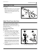
Install Stops at Rows
Insert Stops in Rows
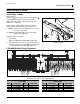
Refer to Figure 3
Stop plates are installed in the one of the two slots
on both sides of the top rear of the opener frame.
Which rows receive plates varies by drill model and
whether left or right wing.
Which slot to use (left or right) is specific to the drill
model and row. The placement charts call it out as:
Stop plate count varies by kit.
7. Select all of:
121-174D OPENER TRANSPORT STOP PLATE
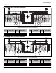
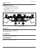
8. Using the placement chart for your drill (below and
on page 4) position each plate in a specified row,
with the center tab in the specified opener slot.
CTA4000HD-8006 (6 inch) Placement
I Inside Toward drill center. Right slot on left wing.
Left slot on right wing.
O Outside Toward wing end. Left slot on left wing.
Right slot on right wing.
Left Wing Right Wing
Row Plate Side Row Plate Side Row Plate Side Row Plate Side
11 Inside (right) 15 Inside (right) 64 Outside (right) 68 Inside (left)
12 Inside (right) 16 Inside (right) 65 - no plate - 69 Inside (left)
13 Inside (right) 17 Inside (right) 66 Inside (left) 70 - no plate -
14 Inside (right) 67 Inside (left)
Figure 3
Installing a Stop
29461
12
1
1
U
D
L
R
B
F
12 1
12
12
01
02
03
04
05
06
07
08
09
10
11
12
13
14
15
16
17
18
19
20
21
22
80
79
78
77
76
75
74
73
72
71
70
69
68
67
66
65
64
63
62
61
60
59
Figure 4
Stop Plate Placement for 6-inch Row Spacing
29459
L
R
B
F