
User Manual


Great Plains Mfg., Inc.
Installation Instructions 5
04/02/2009 221-646M
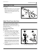
Fasten Stops to Rows
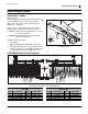
Refer to Figure 7
9. Select all of:
801-025C SCREW HEX 5/16-12X3/4 THD FRM
Insert the screw at the opener frame hole aligned
with the stop plate tab hole, from the side of the
same slot. Drive the self-tapping screw in to a final
torque of:
15 foot-pounds (22 N-m)
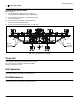
Adjust Wing Primary Seed Hose
Primary seed hoses on the wings are re-routed to
improve clearance. These are the larger 2
1
⁄
2
in (6.4cm)
diameter hoses from the airbox to the tower inlets
(bases). Only Towers 1 (left wing end) and Tower 5 (right
wing end) are involved.
Start with Tower 1 (left wing).
Reconfigure Wing Towers
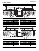
Refer to Figure 8
10. Loosen the hose clamp (not shown) securing the
primary hose (not shown) at the tower inlet .
11. If the vertical plate of the mount is to drill front,
remove the vertical (lower) U-bolts and re-install
the mount so the vertical plate is to the back.
12. Loosen the horizontal U-bolts securing the tower
to the mount.
The tower inlet previously faced forward, perpendic-
ular to the frame tube. Rotate the tower so that the
inlet faces along the frame tube toward drill center.
Adjust the vertical position of the tower so that the
distance from the top of the frame tube to the bot-
tom of the turret plate is 25in (63.5cm). Re-secure
the U-bolts.
13. Repeat step 10 through step 12 for the right wing
and Tower 5. Reset mount plate to back and point
inlet toward drill center.
Figure 7
Securing a Stop
29461
14
U
D
L
R
B
F
14
25in (63.5cm)
25in (63.5cm)
ROTATE ALONG REAR
ROTATE ALONG REAR
FRAME TUBE TOWARD
FRAME TUBE TOWARD
DRILL CENTER
DRILL CENTER
4
Figure 8
Reconfigure (Left) Wing Tower 1
16205
29338
2
5
5
U
D
F
B
L
R
U
D
B
F
R
L
3
2
3
4
5