OPERATOR’S MANUAL Safety Notices ..................................................................................................... 1 Introduction ......................................................................................................... 3 Auto Section Control Features .......................................................................................... 3 Requirements ....................................................................................................................
OPERATOR’S MANUAL System Operation ............................................................................................. 37 Auto Section Main Screen .............................................................................................. Enable Auto Section Control .......................................................................................... Disable Auto Section Control .......................................................................................... Auto Mode ..........
OPERATOR’S MANUAL SAFETY NOTICES Safety notices are one of the primary ways to call attention to potential hazards. An absence of specific alerts does not mean that there are no safety risks involved. This Safety Alert Symbol identifies important safety messages in this manual. When you see this symbol, carefully read the message that follows. Be alert to the possibility of personal injury or death.
OPERATOR’S MANUAL 2 / SAFETY NOTICES Auto Section Control System 11001-1561B-201207
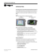
OPERATOR’S MANUAL INTRODUCTION Auto Section Control is an automated row shutoff system that can be added to the IntelliAg planter system to automatically shutoff individual planter sections utilizing a GPS signal as previously planted areas are approached. A dedicated Auto Section Control terminal displays a field map for easy identification of external field boundaries, seeded areas, and nonseeded areas.
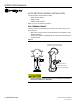
OPERATOR’S MANUAL AUTO SECTION CONTROL INSTALLATION The Auto Section Control cab kit includes: • • • Swath Control display Display mount Display to CAN harness Refer to (Figure 3) harness connections. CAB TERMINAL MOUNT The Auto Section Control terminal is secured in the tractor cab by a ram mount bracket. • Ball mount at top and bottom of bracket allows for orientation in many different positions. Wing bolt in middle of bracket tightens and secures the terminal to the desired position.
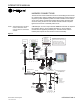
OPERATOR’S MANUAL HARNESS CONNECTIONS The Auto Section Control terminal connects to the IntelliAg tractor harness for communication with the IntelliAg ISO virtual terminal. A GPS receiver is required to provide implement position via CAN or RS232 communication. A row control switch module/clutch folding switch module provides quick access of turning sections on and off when manual override is required. Ignition wire connects to switched power source.
OPERATOR’S MANUAL 6 / INTRODUCTION Auto Section Control System 11001-1561B-201207
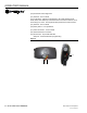
OPERATOR’S MANUAL AUTO SECTION TERMINAL The Auto Section Control terminal displays the field coverage map that shows real-time viewing of the planting operation and indicates the vehicle’s current location. NOTE: All Auto Section Control setup is entered on the IntelliAg virtual terminal or other compatible displays. • Field map appearance on the screen is adjusted using the buttons located on the left and right side of the terminal (Figure 4).
OPERATOR’S MANUAL (12) Decreases screen brightness (13) Terminal - non functional (14) Cycle button - Adjusts the implement to its actual heading (North, South, East, West direction) if the initial tractor movement is reverse, such as backing to a corner. The Flip button also performs the same function.
OPERATOR’S MANUAL AUTO SECTION POWER UP The terminal automatically powers on and off when the ignition switch is powered on and off. At startup, the screen will indicate that the system is initializing until a connection is made with GPS and the IntelliAg PDC controller. When the power is turned off, an orange LED appears in the upper right corner for approximately 1 minute while data is saving and disappears after completing the save. Figure 7 Initializing Auto Initializing....
OPERATOR’S MANUAL Field Map Descriptions: (1) Path-driven field outline - Driving an external field path provides a visual outline of the field. Automatic row shutoff does NOT occur when a section extends past the outline. (2) Seeded area - Areas planted with seed is defined in green.
OPERATOR’S MANUAL TRACTOR/IMPLEMENT POSITION A direction indicator identifies the front of the tractor and direction the tractor is heading.
OPERATOR’S MANUAL 12 / AUTO SECTION TERMINAL Auto Section Control System 11001-1561B-201207
OPERATOR’S MANUAL INTELLIAG PDC SETUP The following IntelliAg PDC screens must be configured to communicate with the Auto Section Control application/terminal and perform Auto Section Control functions. • • • Implement Layout Planter Output Module Clutch Module/Switch Assignment IMPORTANT: Rows must be assigned to a channel before proceeding to implement setup. Row assignment can be verified at the Channel Setup screen.
OPERATOR’S MANUAL PHYSICAL LAYOUT Physical layout of the implement is required to determine the position of the planter control channel in the field. The physical layout of planter center is calculated by measuring the distance from the center of the row units to the hitch pivot point connection. NOTE: If Task Controller functionality is used, these coordinates should already be established. To measure X/Y Coordinates: 1. Stand behind the implement facing tractor.
OPERATOR’S MANUAL 2. At the Physical Layout screen, select the appropriate implement layout type by pressing the tractor/implement graphic. Figure 14 Implement Layout Types 3-Point Hitch Towed Hitch Rigid-Cart Mount Tow-Behind Cart 3. Enter in the table each channel’s X and Y coordinates. X and Y coordinate measurements will vary based on the implement type selected.
OPERATOR’S MANUAL RIGID CART MOUNT An additional -X coordinate measurement from hitch to cart axle is entered in (A1) table.
OPERATOR’S MANUAL PHYSICAL CHECK The Physical Check screen visually displays the implement layout and control channel center as entered on the Physical Layout screen. Use this screen to verify channels are setup correctly. To view Physical Check screen: 1. At the Physical Layout screen, press the Physical Check button. (Figure 18) depicts channel 1 setup in a correct format. Figure 18 Physical Check Screen Setup Correct (Example Only) Channel 1 center (Figure 19) depicts an incorrect Y channel setup: 1.
OPERATOR’S MANUAL CLUTCH CONFIGURATION Clutch module configuration is required to: • • • • Identify how many planter output modules are connected to the IntelliAg system Assign how many outputs are assigned to each output module Assign how many rows are assigned to each output Assign row shutoff module switches to outputs that enable and disable planter sections MULTIPLE TRU COUNT OUTPUT MODULE ASSIGNMENT Output module addresses are a critical parameter used to identify a module’s position on the impleme
OPERATOR’S MANUAL Figure 20 Clutch Delay Times Clutch Type Turn Off Turn On TruCount 0.4 seconds 0.4 seconds Great Plains 0.3 seconds 0.4 seconds Contact DICKEY-john Technical Support at 1-800-637-3302 for recommended shutoff delay times on all other clutches. Figure 21 Clutch Configuration Screen ASSIGNING ROWS The Clutch Configuration screen assigns rows to outputs. As rows are assigned to each output, row numbers automatically populate. 1.
OPERATOR’S MANUAL ASSIGNING ROW SHUTOFF SWITCHES The Clutch Set screen identifies what switches on the row shutoff switch box enable and disable planter sections or outputs. 1. At the Clutch Configuration screen, press the Clutch Set button. Enter which clutch switch will be assigned to an output module to enable and disable planter sections. Figure 23 Clutch Set Screen A red button indicates GPS signal is lost.
OPERATOR’S MANUAL MODULE OUTPUT ASSIGNMENT EXAMPLE 1. 2. 3. 4. Three solenoid outputs to be controlled by Tru Count output module. Number of rows assigned to each output. Row shutoff switches assigned to corresponding outputs. Corresponding row shutoff switches will turn sections on and off.
OPERATOR’S MANUAL 22 / INTELLIAG PDC SETUP Auto Section Control System 11001-1561B-201207
OPERATOR’S MANUAL AUTO SECTION CONTROL SETUP Auto Section Control setup is entered on the IntelliAg virtual terminal. The following Auto Section Control screens must be configured to perform Auto Section Control functions. • • • GPS Setup/Calibration System Setup Selecting a Task GPS SETUP GPS setup and calibration is required for the system to know implement position in relation to the GPS receiver mounting location on the tractor and effectively operate Auto Section control.
OPERATOR’S MANUAL TRACTOR SETUP (FIXED) To determine an accurate reference point between the GPS receiver and Auto Section Control, three distance positions are required: • • • Distance from the GPS receiver antenna mounting location to the rear axle center Distance from rear axle center to the implement hitch Distance from GPS receiver antenna mounting location to implement hitch center of tractor To enter GPS Setup: 1. 2. 3. 4. 5. 6. 7. 8.
OPERATOR’S MANUAL Figure 25 GPS Setup Screen 0.5 8 42 TRACTOR SETUP (ARTICULATED) To determine an accurate reference point between the GPS receiver and Auto Section Control, four distance positions are required: • • • • Distance from the GPS receiver antenna to the front axle center position Distance from front axle center to pivot point Distance from pivot point to rear axle center Distance from rear axle center to implement hitch To enter GPS Setup: 1. 2. 3. 4. 5. 6. 7. 8.
OPERATOR’S MANUAL 11. Measure the distance from the center of the receiver to the distance from the center front axle. Enter the distance into the Axle to Receiver input box. 12. Measure the distance from the center of the front axle to the center of the tractor pivot point. Enter the distance into the Front to Pivot input box. 13. Measure the distance from the center of the rear axle to the center of the tractor pivot point. Enter the distance into the Pivot to Rear input box. 14.
OPERATOR’S MANUAL 6. 7. 8. 9. When the Set Reference button is pressed, the Auto Section Control terminal will indicate tractor position and mark a blue line on the screen as a site of reference. It is important that the tractor be perpendicular to the blue line to drive straight across the line. Follow the onscreen instructions on the IntelliAg virtual terminal and begin driving forward at the desired planting speed.
OPERATOR’S MANUAL • • When diagnosing system accuracy issues, it is recommended to re-run the GPS calibration. In the event a new software version is loaded in the Auto Section Control or GPS receiver, the GPS calibration should be executed as the software update could cause the GPS lag value to change.
OPERATOR’S MANUAL FIELD PREPARATION SETTING OVERLAP An automatic delay or advance can be configured to enable and disable planter sections when approaching or leaving an area by setting a Run In/ Run Out Overlap or Skip and a side-to-side overlap. A distance is entered in inches/metric to enable this feature. RUN IN OVERLAP A Run In Overlap sets the distance (inches) to automatically delay section shutoff when a planted area is entered.
OPERATOR’S MANUAL Figure 29 Side-to-Side Overlap Adjustment with Planter (Single Section) } } Skip } Overlap 50% Overlap Adjustment Overlap 100% Overlap Adjustment Example: One-to-One Row/Clutch Assignment A one-to-one row/clutch assignment set at 100% turns individual rows on and off with an overlap and no gap. As the side-to-side overlap percentage decreases, the overlap decreases and the gap increases.
OPERATOR’S MANUAL IMPORTANT FUNCTIONALITY NOTES The below situations can effect how Run In/Run Out functionality operates in the field. Take into account the following when determining what values to enter on the System Setup screen. • • • • • • • Auto Section Control System 11001-1561B-201207 A Run In/Run Out value of “0” turns on and off sections as soon as the planter rows reach an area equal to 50% of the programmed row spacing entered on the IntelliAg PDC setup of Row I/O.
OPERATOR’S MANUAL To Enter a Run In and Run Out Settings and Overlap: Run In Button Run Out Button 1. At the Auto Section Control Main screen, press the System Setup button. 2. Press the Run In and/or Run Out buttons to cycle between Skip or Overlap. 3. Enter the amount of Run In and/or Run Out in inches into the appropriate input boxes. 4. Press the Increase and Decrease % Side-to-Side buttons to adjust to desired overlap and gap percentage from 50% to 100%.
OPERATOR’S MANUAL LOAD A TASK A task must be created or selected first before Auto Section Control will operate. A task can be created at the Auto Section Control menu on the IntelliAg virtual terminal or existing tasks established in Task Controller can be imported using an SD card. CREATE TASK 1. At the Auto Section Control Main screen, press the Select Task button. 2. At the Select Task screen, press the New Client button. 3. Press the New Client input box and enter name using the keypad. 4.
OPERATOR’S MANUAL IMPORT A TASK OR FIELD BOUNDARY FILE Client, Farm, Field, and Events created in Task Controller or a farm management software tool can be saved and imported into the Auto Section Control terminal eliminating the step of re-creating a task. Tasks and boundary file data are saved to an SD card inserted into the IntelliAg terminal and then transferred to the Auto Section Control terminal. The Import button only appears when Task Controller is enabled on the IntelliAg VT with an SD card.
OPERATOR’S MANUAL 8. When transfer is complete, the number of clients, farms, fields, tasks, and field boundaries appear on screen. 9. Press the Back button to return to the Select Task screen. 10. Select the desired client, farm, field, task, and field boundary. A Boundary Exists icon appears when a boundary file (created with farm management software) is available. 11. Press the Open Task button.
OPERATOR’S MANUAL OVERWRITE FIELD BOUNDARY An Overwrite Field Boundary screen appears if the Auto Section Control terminal already has the existing boundary with the same file name associated with a field. – Press the OK button to overwrite the existing boundary. – Press the Cancel button to retain the existing boundary. Figure 35 Overwrite Field Boundary AUTO SECTION CONTROL STATUS The Auto Section Control terminal will be in ready mode at the Select Task screen.
OPERATOR’S MANUAL SYSTEM OPERATION AUTO SECTION MAIN SCREEN When a task is loaded, the Auto Section Control Main Menu displays on the IntelliAg virtual terminal and provides a visual representation of implement section status that can be controlled from this screen. NOTE: Pressing a section indicator button represents what action will occur when pressed, not the current action.
OPERATOR’S MANUAL 8. Current Task Active task running 9. GPS signal GPS signal strength 10. Satellites Number of active satellites 11. System status bar Provides current status of Auto Section Control 12. Right Section Indicator buttons define all sections in the right group to be controlled by the right Auto/On/Off button when moved. The color of the left and right indicator identifies the action (on or off) to occur when section indicators are moved.
OPERATOR’S MANUAL ENABLE AUTO SECTION CONTROL To enable Auto Section Control: 1. Once a task is selected, press the Open Task button. 2. At the Auto Section Control Main Menu screen enable the following system functions: – Lower implement into the ground – Turn master switch on – Verify all clutch section switches are on IMPORTANT: Vehicle speed must be greater than the shutoff speed set at the IntelliAg Speed Setup screen. 3. Begin driving at desired planting speed. 4.
OPERATOR’S MANUAL AUTO MODE Auto mode automatically enables and disables individual planter sections utilizing a GPS signal as previously planted areas or boundaries are approached. As planted areas and boundaries are approached, the Auto Section Control Main Menu screen indicates which outputs turn on and off and the row control switch module/clutch folding module indicator lights automatically turn on and off. Sections can be forced OFF in Auto mode.
OPERATOR’S MANUAL 4. Left Section Indicator buttons define all sections in the left group when moved. The color of the left and right indicator identifies the action (on or off) to occur when section indicators are moved. 5. Right Section Indicator buttons define all sections in the right group when moved. The color of the left and right indicator identifies the action (on or off) to occur when section indicators are moved. 6.
OPERATOR’S MANUAL the left and right indicator identifies the action (on or off) to occur when section indicators are moved. 5. Right Section Indicator buttons define all sections in the right group to be controlled by the right Auto/On/Off button when moved. The color of the left and right indicator identifies the action (on or off) to occur when section indicators are moved. 6.
OPERATOR’S MANUAL The system cannot differentiate between a marked and already planted area. Therefore, when planting the marked headland, the section control must be in manual. The field map planting area will appear in blue which is the indication of overplanting. However, overplanting is not occurring since the first pass was marked and no seeds were dropped. If only the inner most headland is marked, this is the only headland that requires the control to be in manual.
OPERATOR’S MANUAL Figure 43 Auto No GPS OUT OF FIELD RANGE An Out of Field screen on the Auto Section Control terminal occurs when the field is outside of range to display on the screen. Select the correct field or start a new task to continue.
OPERATOR’S MANUAL TERMINAL STORAGE CAPACITY All created and imported fields are stored on the Auto Section Control terminal. Storage capacity is indicated on the Auto Section Control terminal Main Menu screen. When full, storage can be cleared or deleted by clearing tasks or deleting files. Task or files cannot be exported. TIP: It is recommended that imported and created fields are cleared after use to avoid the system from running slow. CLEAR TASK 1.
OPERATOR’S MANUAL DELETE/RENAME FILES NOTE: Individual clients, farms, fields, and tasks can be renamed at the Rename/Delete screen by pressing the appropriate yellow selection box. Use virtual keypad to enter new name. Individual clients, farms, fields, and tasks can be deleted. 1. At the Select Task screen, select the desired client, farm, field, or task to delete. 2. Press the Rename/Delete button. 3. At the Rename/Delete screen, press the appropriate Delete button. 4.
OPERATOR’S MANUAL DIAGNOSTICS The Diagnostics screen provides information about the Auto Section Control software version and GPS status. Information on the screen cannot be edited. Press the Diagnostics button to access the GPS Status and System Information screens. GPS STATUS The GPS Status screen provides information about the current status of the GPS functionality used for troubleshooting. Information on the screen cannot be edited. 1.
OPERATOR’S MANUAL SYSTEM INFORMATION The System Information screen provides system software version information. Information on this screen cannot be edited. 1. At the Diagnostics screen, press the Information button to access the System Information screen.
OPERATOR’S MANUAL CLUTCH SECTION CHECK A recommended pre-test to verify correct module and clutch assignment ensures that clutches turn on and off appropriately. To perform test: Start Test 1. At the Diagnostics screen, press the Section Check button. 1. Enter the cycle time duration of turning clutches on and off. 2. Select the type of test to perform – All output test – Single output test 3. Press the Start Test button to begin test. 4. Press the Stop Test button to end test.
OPERATOR’S MANUAL 50 / DIAGNOSTICS Auto Section Control System 11001-1561B-201207
OPERATOR’S MANUAL TROUBLESHOOTING FIRST PASS NEXT TO BOUNDARY IS SHUTTING OFF ROWS WHEN USING BOUNDARY FILES • Outside clutches will turn off when a section width is outside the boundary based on the side-to-side overlap setting. To correct, run outer pass in Manual mode and widen boundary file in PC software to prevent this issue next time. This scenario is typically prevalent when using WAAS.
OPERATOR’S MANUAL • Clutch assignment may be incorrect. – Verify that output modules have been correctly assigned to rows at the Module Configuration screen. – Verify that row shutoff switches are correctly assigned to corresponding outputs. – Run a Clutch Section check to verify the order of clutch sections shut on and off correctly (refer to Diagnostics screen). auto section control screen shows gaps in swath pattern (start/stop) – Driving to wide. – GPS accuracy issue.
OPERATOR’S MANUAL SWATH PATTERN IS OFFSET FROM THE SWATH DIRECTION INDICATOR • • • Implement measurements could be incorrect. – Verify that measurements were entered as described at Physical Layout screen. – X measurements should be taken from the hitch pivot point to where the seed is placed in the ground. – Y coordinates are measured from implement center to the center of each channel. Check row pattern setup at IntelliAg I/O screen. Check Physical Layout screen to verify layout is correct.
OPERATOR’S MANUAL IMPORTANT: OmniSTAR correction types require paid subscription. For an AgGPS 252 or 332 receiver, select either OmniSTAR HP/XP or OmniSTAR HP/XP-VBS. Refer to Ag GPS Autoseed fast restart technology.
OPERATOR’S MANUAL ERROR CODES Various alarm conditions may be presented whenever the system encounters an abnormal condition or detects a specific alarm. Alarms are typically in a full screen display describing the alarm and, dependent upon the alarm type, may give instructions on how to fix the alarm. Each alarm type has an associated alarm number . Some alarms require a specific action before the alarm condition will cease. In these cases, instructions are indicated on the alarm display.
OPERATOR’S MANUAL APPENDIX A AGCO GTA CONSOLE AGCO tractors with a factory installed cab harness and GTA console requires the GTASWATHKIT. This kit contains the required harnesses that connect to the GTA console and auxiliary power connector in the cab.
OPERATOR’S MANUAL APPENDIX B JOHN DEERE GS2 CONSOLE John Deere tractors with a factory installed cab harness and GS2 console requires the GS2SWATHKIT. This kit contains the required harnesses that connect to the GS2 console and auxiliary power connector in the cab.
OPERATOR’S MANUAL DEERE GS2 CONSOLE CAB HARNESS CONNECTIONS 1. Standing on the outside of the cab near the Starfire GPS receiver, remove the dust plug connector on the GPS receiver harness. IMPORTANT: Do not unplug the male connector of the GPS receiver harness connected to the John Deere cab/electronics. Figure 52 Remove GPS Receiver Dust Plug from Starfire Receiver Harness Do not unplug male connector of GPS receiver harness 2.
OPERATOR’S MANUAL 3. Inside the cab, connect CFM/RSM Module harness part number 46798-0335 to the mating 4 pin connector of the GS2 console harness. Figure 54 Connect CFM or RSM Harness to GS2 Console 4. Connect the mating connectors of the Auxiliary Interface Module harness part number 46798-0336 to the CFM/RSM Switch Module harness part number 46798-0335.
OPERATOR’S MANUAL 5. Connect the Auto Section Control harness part number 46798-0337 to the mating connector of the Auxiliary Interface harness part number 46798-0336. Figure 56 Connect Auto Section Control Harness to Aux Interface Harness 6. Plug in the Auxiliary Power 3 pin connector of the Auto Section Control harness part number 46798-0337 to the auxiliary power in the cab.
OPERATOR’S MANUAL 7. Connect the RS232 connector from the Starfire Interface cable to the RS232 connector of the Auto Section Control harness part number 46798-0337.
OPERATOR’S MANUAL 62 / ERROR CODES Auto Section Control System 11001-1561B-201207
Dealers have the responsibility of calling to the attention of their customers the following warranty prior to acceptance of an order from their customer for any DICKEY-john product.