
Manual


OPERATOR’S MANUAL
Auto Section Control System
11001-1561B-201207
INTRODUCTION / 5
HARNESS CONNECTIONS
The Auto Section Control terminal connects to the IntelliAg tractor harness
for communication with the IntelliAg ISO virtual terminal. A GPS receiver is
required to provide implement position via CAN or RS232 communication.
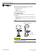
A row control switch module/clutch folding switch module provides quick
access of turning sections on and off when manual override is required.
Ignition wire connects to switched power source.
NOTE: Refer to Appendix A and B for
harness connections when
using an AGCO or John Deere
Console.
A DICKEY-john Tru Count output module WSMB and harness are required
for interfacing with Tru Count solenoid modules. Tru Count solenoid
modules are not supplied by DICKEY-john. The below items outlined
indicate parts required for Auto Section Control functionality.
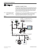
Figure 3
Harness Connections
Auto Section
Control Terminal
ISO
Tractor
Hitch
WSMT 2 ‘T’ Harness
467980850
Add a CAN Extension
or
CAN Terminator
WSMB
Tru Count
Output Module
Tru Count
Solenoid
Modules
(available from
Tru Count)
Tru Count
Clutch Harness
467983505
IntelliAg
Virtual Terminal
Hitch Extension
Harness
46798013x
Battery
Tractor
Power
Harness
467980455
CFM Switch
Module or
Row Control
Switch Module
467984264S1
WSMT 2
PDC Module
Tractor ECU
Master
Switch
Radar
RS232 (not
used with
Auto Section
Control)
Tractor A1
Harness
467980451A
RSM/CFM to
CAN Harness
467980330
Auto
Section
Terminal
Interface
Harness
467980458
GPS Receiver
(See Note)
Ignition
NOTE: GPS receiver connects
direct to RS232 on Auto Section
Terminal harness. Refer to
Auto Section Control Setup to
transmit GPS signal over CAN.
: