
Manual


Great Plains Mfg., Inc.
2 Electro-Hydraulic Control Option
506-605M 06/09/2008
Assembly Instructions
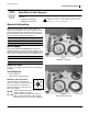
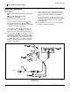
Mount Tube Bracket
Refer to Figure 3
1. Select one each:
506-357D C-SECTION NOZZLE TUBE BRACKET
806-001C U-BOLT 3/8-16 X 2 X 4
806-107C U-BOLT 5/16-18 X 1 17/32X2 1/8
and two sets:
803-068C NUT HEX FLANGE 3/8-16 PLT
803-199C NUT HEX FLANGE 5/16-18 PLT
Position mounting bracket the same distance to
left of center posts as existing mounting bracket
is to right of posts.
Use 3/8in hardware ( , ) at boom frame, and
5/16in hardware ( , ) at nozzle tube.
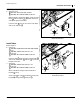
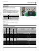
Prepare valve and Bracket
Refer to Figure 6
If the decal is already applied, skip to Step 3.
2. Select one each:
510-022D FASSE VALVE BLOCK MTG PLATE
818-339C DECAL WARNING HIGH PRESSUR SML
Clean and dry the back side of the bracket . Peel
the backing paper from the decal . With the
bracket break up and away from you, position the
decal at the upper left corner. Apply it. Smooth out
any air bubbles by applying pressure with a clean
cloth.
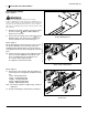
If the elbows are already installed, skip to Step 5.
3. Select one each:
833-215C FASSE VALVE BLOCK ASSY 302-451
and two:
811-169C EL 9/16MJIC 9/16FJIC
Install the elbows on the end ports of the valve
block, facing away from the back of the valve.
4. Apply some hydraulic fluid to the cone and threads of
the male fittings. Torque 9/16 JIC fittings to 18-20 ft-
lbs (24-27 N-m).
Figure 3
Mounting Bracket
17525
12
1
2
3
4
17
20
16
18
U
D
L
R
B
F
12
18
20
16
17
12
3 4
18
16
20 17
Figure 4
Decal and Elbows
28172
14
22
23
21
14
22
14
22
23
21
21