
Manual


Great Plains Mfg., Inc.
Installation Instructions 3
06/09/2008 506-605M
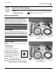
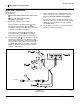
Refer to Figure 5
5. Select two sets:
802-216C HHCS 3/8-16X2 3/4 GR5
803-068C NUT HEX FLANGE 3/8-16 PLT
With the break of the bracket up, orient the valve
block with the elbows up and the back of the
valve block against the bracket.
Insert the bolts from the front of the valve block,
and secure with nuts .
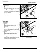
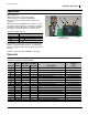
Install Valve
Refer to Figure 6
6. Select one:
506-368D TUBE ELEC/HYD MTG FOR CF600
and two:
806-004C U-BOLT 3/8-16 X 2 X 2 3/4
and two sets:
803-068C NUT HEX FLANGE 3/8-16 PLT
Place the tube under the valve on the bracket ,
and secure with U-bolts and nuts . Center the
bracket on the tube.
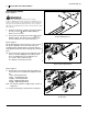
7. Select two:
806-004C U-BOLT 3/8-16 X 2 X 2 3/4
and two sets:
803-068C NUT HEX FLANGE 3/8-16 PLT
Orient valve block facing forward, with break in
bracket at top.
Secure tube to new and existing nozzle tube
bracket , using U-bolts and nuts .
Figure 5
Mount Control Valve
18369
23
14
15
16
U
D
L
R
B
F
21
15
16
14
23 21
15
16
Figure 6
Install Control Valve
18366
13
19
16
14
U
D
L
R
B
F
4
16
16
13
19
16
13 14
19 16
19
16
14
13 12
41916