
Manual


Great Plains Mfg., Inc.
6 Electro-Hydraulic Control Option
506-605M 06/09/2008
Install Cab Components
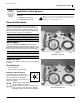
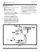
Refer to Figure 11
16. Select one:
833-216C FASSE HANDLE RCS ASSY 1020C
or
833-217C FASSE SWITCH BOX
depending on kit ordered.
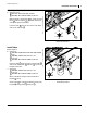
17. Mount valve controller in tractor cab.
If the kit contains a joystick controller , select
appropriate U-bolt fasteners from supplied
assortment, and secure the controller to the hydrau-
lic remote lever for boom operations.
If kit contains a switch box , mount box in an
accessible location in tractor cab. Kit includes
bracket, but does not include mounting fasteners.
18. Connect power leads from controller to a 12-volt,
negative-ground power source. To prevent valve
from draining tractor battery, connect power leads to
fuse panel, key switch or other source that is not
energized when tractor is off. Connect red lead to
positive (+) terminal and black lead to negative (-)
terminal or other ground.
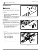
19. Route controller harness to hitch and mate with
sprayer harness. If slack is insufficient, select one:
833-219C FASSE HARNESS EXTENSION
Insert it in the circuit to provide more slack. Tie up
any excess cable so that it cannot touch the ground
during operations (or when the tractor used with
other implements).
20. Secure harness to tractor so it is not damaged dur-
ing tractor and boom operations.
Figure 11
Cab Connections
17526
9
To Sprayer
8
24
25
27
24
25
24
8
25
9
27