
Manual


Great Plains Mfg., Inc.
Installation Instructions 7
06/09/2008 506-605M
Operations
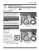
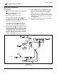
Refer to Figure 12
Switch box switches are 2-position toggles.
Joystick switches are 2-position push-button.
They remain in their currently selected status until
changed.
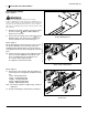
When power is being supplied to the controller, an indi-
cator lamp at each switch is on if the switch is engaged
and power is being supplied to the assigned solenoids.
An indicator is off is the switch is off, or power is off.
The switch assignments are:
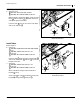
The hydraulic circuit lever is normally left in the Neutral
position, to hold the cylinder positions. To fold/unfold or
lift/lower, engage the switch for that cylinder, and operate
the lever.
Cylinders may be operated individually or as groups.
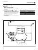
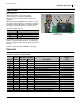
Parts List
506-584A ELEC/HYD KIT JOY STICK
506-585A ELEC/HYD KIT SWITCH BOX
Switch Color (Valve Port) Cylinder Controlled
Green Left Boom Fold/Unfold
Yellow Elevator Lift/Lower
Red Right Boom Fold/Unfold
Callout
Part
Number
Quantity in Kit 506-
Description
Torque
Value
506-584A 506-585A
506-605M 1 1 MANUAL FASSE VALVE INSTALL
506-357D 1 1 C-SECTION NOZZLE TUBE BRACKET
506-368D 1 1 TUBE ELEC/HYD MTG FOR CF600
510-022D 1 1 FASSE VALVE BLOCK MTG PLATE
802-216C 2 2 HHCS 3/8-16X2 3/4 GR5 31 ft-lbs / 32 N-m
803-068C 12 12 NUT HEX FLANGE 3/8-16 PLT 31 ft-lbs / 32 N-m
803-199C 2 2 NUT HEX FLANGE 5/16-18 PLT 17 ft-lbs / 24 N-m
806-001C 1 1 U-BOLT 3/8-16 X 2 X 4 31 ft-lbs / 32 N-m
806-004C 4 4 U-BOLT 3/8-16 X 2 X 2 3/4 31 ft-lbs / 32 N-m
806-107C 1 1 U-BOLT 5/16-18 X 1 17/32X2 1/8 17 ft-lbs / 24 N-m
811-169C 2 2 EL 9/16MJIC 9/16FJIC 18-20 ft-lbs / 24-27 N-m
818-339C 1 1 DECAL WARNING HIGH PRESSUR SML
833-215C 1 1 FASSE VALVE BLOCK ASSY 302-451
833-216C 1 FASSE HANDLE RCS ASSY 1020C
833-217C 1 FASSE SWITCH BOX
833-218C 1 1 FASSE HARNESS
833-219C 1 1 FASSE HARNESS EXTENSION
Figure 12
Switch Functions
28173
Y
G
R
G
Y
R
G 2
Y 1
R 3
11
12
13
14
15
16
17
18
19
20
21
22
23
24
25
26
27