
Manual


7’ & 10’ End Wheel No-Till Clutch Linkage 152-156M 5/3/96
-1
Great Plains Mfg., Inc.
Section 2 Assembly & Set-Up
Section 2 Assembly & Set-Up
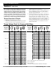
Torque Values Chart for Common Bolt Sizes
in-tpi
1
N · m
2
ft-lb
3
N · m ft-lb N · m ft-lb mm x pitch
4
N · m ft-lb N · m ft-lb N · m ft-lb
1/4" - 20 7.4 5.6 11 8 16 12 M 5 X 0.8 4 3 6 5 9 7
1/4" - 28 8.5 6 13 10 18 14 M 6 X 1 7 5 11 8 15 11
5/16 - 18 15 11 24 17 33 25 M 8 X 1.25 17 12 26 19 36 27
5/16" - 24 17 13 26 19 37 27 M 8 X 1 18 13 28 21 39 29
3/8" - 16 27 20 42 31 59 44 M10 X 1.5 33 24 52 39 72 53
3/8" - 24 31 22 47 35 67 49 M10 X 0.75 39 29 61 45 85 62
7/16" - 14 43 32 67 49 95 70 M12 X 1.75 58 42 91 67 125 93
7/16" - 20 49 36 75 55 105 78 M12 X 1.5 60 44 95 70 130 97
1/2" - 13 66 49 105 76 145 105 M12 X 1 90 66 105 77 145 105
1/2" - 20 75 55 115 85 165 120 M14 X 2 92 68 145 105 200 150
9/16" - 12 95 70 150 110 210 155 M14 X 1.5 99 73 155 115 215 160
9/16" - 18 105 79 165 120 235 170 M16 X 2 145 105 225 165 315 230
5/8" - 11 130 97 205 150 285 210 M16 X 1.5 155 115 240 180 335 245
5/8" - 18 150 110 230 170 325 240 M18 X 2.5 195 145 310 230 405 300
3/4" - 10 235 170 360 265 510 375 M18 X 1.5 220 165 350 260 485 355
3/4" - 16 260 190 405 295 570 420 M20 X 2.5 280 205 440 325 610 450
7/8" - 9 225 165 585 430 820 605 M20 X 1.5 310 230 650 480 900 665
7/8" - 14 250 185 640 475 905 670 M24 X 3 480 355 760 560 1050 780
1" - 8 340 250 875 645 1230 910 M24 X 2 525 390 830 610 1150 845
1" - 12 370 275 955 705 1350 995 M30 X 3.5 960 705 1510 1120 2100 1550
1-1/8" - 7 480 355 1080 795 1750 1290 M30 X 2 1060 785 1680 1240 2320 1710
1 1/8" - 12 540 395 1210 890 1960 1440 M36 X 3.5 1730 1270 2650 1950 3660 2700
1 1/4" - 7 680 500 1520 1120 2460 1820 M36 X 2 1880 1380 2960 2190 4100 3220
1 1/4" - 12 750 555 1680 1240 2730 2010
1 3/8" - 6 890 655 1990 1470 3230 2380
1
in-tpi = nominal thread dia. in inches-threads per inch
1 3/8" - 12 1010 745 2270 1670 3680 2710
2
N· m = newton-meters
1 1/2" - 6 1180 870 2640 1950 4290 3160
3
ft-lb= foot pounds
1 1/2" - 12 1330 980 2970 2190 4820 3560
4
mm x pitch = nominal thread dia. in millimeters x thread pitch
5.8 8.8 10.9
Class 5.8 Class 8.8 Class 10.9
Bolt Head Identification
Bolt Size
(Metric)
Grade 2 Grade 5
Grade 8
Bolt Head Identification
Bolt Size
(Inches)
Section 1 Safety Rules
Most accidents are the result of negligence and careless-
ness, usually caused by failure of the operator to follow
simple but necessary safety precautions. The following
safety precautions are suggested to help prevent such
accidents. The safe operation of any machinery is a big
concern to consumers and manufacturers. Your Clutch
Linkage Update Kit have been designed with many built-
in safety features. However, no one should operate this
product before carefully reading this Operators Manual.
General Operation & Repair
1. DO NOT exceed 20 mph transport speed.
2. Areas of this drill can be dangerous and can cause bodily
harm if not properly used or guarded. Stay away from
equipment when it is in operation!
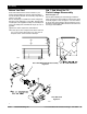
3. Before working on, servicing or making adjustments on
the drill, ALWAYS disengage power, shut off engine,
make sure all moving parts have stopped, and all pres
-
sure in the system is relieved.
4. Escaping fluid under pressure can have sufficient force
to penetrate the skin. Check all hydraulic lines and hoses
before applying pressure. Fluid escaping from a very
small hole can be almost invisible. Use paper or card
-
board, not body parts, to check for suspected leaks. If in-
jured, seek medical assistance from a doctor that is
familiar with this kind of injury. Foreign fluids in the tis
-
sue must be surgically removed within a few hours or
gangrene will result.