
Manual

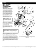


7’ & 10’ End Wheel No-Till Clutch Linkage 152-156M 5/3/96
3
Great Plains Mfg., Inc.
Assembly
New 10’ End Wheel
No-Till Clutch
Linkage Assembly
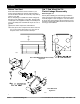
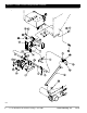
Refer to Figure 2-6:
Attach the clutch mounting plate
(#8) to the bottom of the hanger
sub-weldment using the existing
hardware that fastens the gearbox
on. Then fasten the clutch rod sup
-
port (#5) to the hanger using
5/16"-18 x 1" bolts (#13), 5/16"
washers, & nuts.(#14,18,22). Pre-
assemble the clutch rod weldment
(#4), and inside cotter pin (#23).
Slide the inside retaining washers
(#21) & pivot bushing (#7) onto the
clutch rod. Insert this assembly into
the hole of the mounting plate (#8)
and rod supports (#5). Hold this in
place with a retaining washer (#21)
and cotter pin (#23). Slip the clutch
rod spacer (#9) over the outside end
of the clutch rod and through the
support plate. Retain it in place with
the rod push arm, (#2) retaining
washer (#21) and cotter pin (#23).
NOTE: The push arm (#2)
must be in line with the arm on
the clutch rod (#4).
Fasten the clutch tab (#10) to the clutch slide plate using
3/8"-16 x 1" bolts (#11) with 3/8"-16 Nylock nuts (#17).
NOTE: Assemble the clutch tab adjustment (#6)
with the ear of the clutch tab (#10) in the adjustment
slot.
Add the clutch tab adjustment (#6) to the clutch mount-
ing plate (#8) using 3/8"-16 x 1 1/4" bolts (#12) and 3/8"
hardware (#16,19,20) but do not fully tighten.
Attach the link pull arm (#1) to the clutch and to the
clutch rod (#4) with a 3/8"-16 Nylock nut (#17). Adjust
the tab plate (#6) to correctly engage/disengage the
clutch assembly during normal field operations. This can
be done by raising and lowering the hydraulics and care
-
fully watching the engaging/disengaging of the clutch.
After it is adjusted, tighten the adjustment plate (#6) in
place.
13807
New 10’ End Wheel No-Till Clutch Linkage Assembly
Figure 2-6