
User guide


Great Plains Mfg., Inc.
Installation Instructions 1
©Copyright 2006 Printed 01/23/2008 401-463M
Fan Butterfly Valve Kit
Yield-Pro Hydraulic Fans
Used with:
• Pre-2007 12- and 16-row Yield-Pro Planters
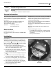
General Information
These instructions explain how to install the Fan Butterfly
Valve Kit. This feature is now standard on new products,
and is available as an upgrade to provide additional air
flow control.
The kit also includes a miscellaneous update, of 6
decals, applicable to older Yield-Pro planters.
These instructions apply to:
Before You Start
Each kit converts one fan.
For each kit, inventory the contents per the “Parts List”
on page 4.
Establish that your fan has the necessary pre-drilled and
tapped holes for mounting kit components; some fans
may not. More typically, the holes are present and con-
tain a bolt and plastic plugs.
If necessary, move the implement to a dry well-lighted
location suitable for disassembly.
Park and secure the implement. Secure the tractor if left
connected.
Disconnect any hydraulic and electrical power to the
implement
Have the following tools at hand:
•
1
⁄
4
-20 UNC tap and tap wrench, #7 drill bit and drill
• Basic hand tools (including a right-angle flat-bladed
screwdriver)
• Fine-tip washable marker
Installation
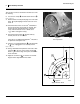
Refer to Figure 2
Inspect the mounting orientation of your hydraulic fan.
The flange has an eccentric shape, and the narrowest
part of the flange needs to be adjacent to the location
where the new fan control will go . If it is not mounted
this way, complete the following steps:
1. Remove and save the 6 bolts holding the cap
screen on the fan cage (not shown). Note the orien-
tation of any fan block baffle on the cage.
2. Disconnect the fan sensor connector, remove any
protective grommet at the screen hole, and pull the
sensor lead inside the cage.
3. Remove and save the bolts holding the flange to the
fan .
4. Rotate the fan into the orientation depict at right.
Re-insert the flange mounting bolts and secure.
5. If the fan has a blocking baffle, remove its fasteners
and re-mount it as it was previously oriented.
6. Cut a new hole for the sensor lead, at screen bot-
tom, but clear of the operating area for the new con-
trol. Re-insert grommet. Seal old hole.
7. Re-attach cage screen cap.
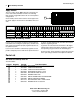
401-457K Fan Butterfly Valve Kit
(order one kit per fan)
Figure 1
Fan Flange
25392
3
2
1
1
2
3