
User guide


Great Plains Mfg., Inc.
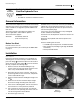
2 Fan Butterfly Valve Kit
401-463M 01/23/2008
The fan valve control is mounted on the inlet face of the
fan housing.
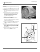
8. Loosen hose clamp and remove 6in fan hose .
Refer to Figure 2
9. Remove bolts or knock plastic plugs out of fan shaft
holes . Any bolts/plugs in these holes are not re-
used.
10. Check that these holes are at least
3
⁄
8
in diameter.
Use the fan shutter control shaft to check fit. The
shaft must pass through both holes, and pivot
freely. If the shaft does not fit, or binds, use a
13
⁄
32
in drill to enlarge the hole(s).
11. Unscrew bolt at bolt hole . Any bolt and any
washer present are not re-used.
If the hole is not drilled and tapped for
1
⁄
4
-20, drill a
#7 pilot hole and tap the hole.
12. If there is a cast detail similar to on the back side
at , leave it plugged. It is not used by this kit.
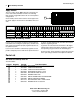
Refer to Figure 3
13. Using a washable fine-tip marker and a ruler, draw
two lines on the face of the shutter control .
Each is
1
⁄
2
in from the edge of the plate, and on the
shaft centerline.
14. Apply the scale decal so that the “0” and “90”
degree marks align with the lines drawn.
Figure 2
Fan Preparation
25136
3
3
4
5
2
1
1 2
3
4
4
5
Figure 3
Apply Decal to Scale
25137
0.5in
0.5in
12
4
4
18
412
18