
User guide


Great Plains Mfg., Inc.
4 Fan Butterfly Valve Kit
401-463M 01/23/2008
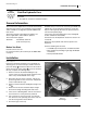
Apply Decals
The new caution decals are placed on the back face
of the main toolbar, between row units. The following
table contains suggested locations “D” for various planter
configurations.
Clean and dry each location. Peel the release paper from
the decal. Apply it and smooth out air bubbles with a soft
cloth.
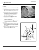
Using the Butterfly Valve
In most cases, Great Plains anticipates that the butterfly
valve will be left at 0 degrees (wide open), and that seed
flow and fan speed will be properly regulated by the trac-
tor hydraulic system.
If your tractor is unable to satisfactorily regulate, but can
produce adequate pressure and flow to operate the fan at
or above recommended speeds, then this valve may be
helpful in regulating air flow.
In general, the valve has little effect below a 20 degree
setting and too much effect above 45 degrees. The prac-
tical operating range is between 20 and 30 degrees.
For best results, always attempt to operate the fan motor
at the rpm settings called for in the Operator’s Manual.
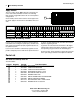
Parts List
401-457K Fan Butterfly Valve Kit
Your kit includes:
0
1
0
2
0
3
0
4
0
5
0
6
0
7
0
8
0
9
1
0
1
1
1
2
1
3
1
4
1
5
1
6
12-Row DDDDDD
12-Row Twin DDDDD
16-Row D D D D D D
16-Row Twin D D D D D D
17
17
Callout Quantity Part No. Part Description
1 401-463M This manual
1 401-363H CRARY FAN SHUTTER
1 411-030D CRARY FAN SHUTTER DISK
2 801-055C SCREW RD HD 10-24 X 1 PLT
2 803-268C NUT HEX NYLOCK 10-24 PLT
2 804-054C WASHER LOCK #10
6 838-993C DECAL DO NOT LOCK UP REAR ROW
1 848-020C DECAL FAN BAFFLE INDEX
1 801-151C SCR HEX SELF TAP 1/4-20X1TYPEF
1 804-075C WASHER FLAT 1/4 USS PLT
11
12
13
14
15
16
17
18
19
20
Great Plains Manufacturing, Inc.
Corporate Office: PO Box 5060
Salina, KS 67402-5060 USA