
Manual


Great Plains Mfg., Inc. Front Parts Installation Instructions 3
2014-04-15 Front Parts 194-033M
Hydraulic Pressure Relief
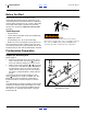
High Pressure Fluid Hazard:
Only trained personnel should work on system hydraulics!
Escaping fluid under pressure can have sufficient pressure to
penetrate the skin, causing serious injury. Avoid the hazard by
relieving pressure before disconnecting hydraulic lines. Use a
piece of paper or cardboard, NOT BODY PARTS, to check for
leaks. Wear protective gloves and safety glasses or goggles
when working with hydraulic systems. If an accident occurs,
see a doctor immediately. Any fluid injected into the skin must
be surgically removed within a few hours or gangrene will
result.
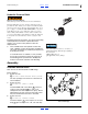
Installation of this kit may require, at a later step, breaking
sealed hydraulic connections at quick-disconnect
couplers. It is crucial to safety that these lines be
depressurized.
3. If the available tractor has hydraulic circuits with
“float” capability, connect the Transport and Opener
Lift circuits, and relieve any residual system pressure
by floating the circuits.
If no suitable tractor is available, “crack” (carefully
loosen) the connections for both Lift circuits the at
the bleeding points specified in the drill Operator
manual. Leave them cracked for later bleeding.
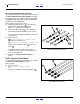
Assembly
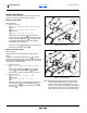
Assemble Selector Valve
Note: Do not use thread sealant on ORB fittings.
Refer to Figure 3
4. Select: one new
810-274C DOUBLE SELECTOR VALVE 3/4FORB
The face openings of the valve are to machine left
after installation.
5. Select: two new
811-063C EL 3/4MJIC 3/4MORB
Install the ORB ends of the elbows in the face
(center) of the valve body (“1” and “2” are
stamped into the valve body at those ports). Before
tightening the jam nuts, orient the JIC ends so that
they face forward when the valve is mounted.
6. Select: four new
811-021C AD 1/2FNPTS 3/4MORB
Install the adaptors in the end ports of the valve
body (ports stamped “1A”, “1B”, “2A” and “2B”).
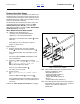
Bleed only at:
JIC (Joint Industry Conference, 37° flare) or
NPT (National Pipe Thread, tapered) fittings.
Never bleed at:
ORB (O-Ring Boss) or
QD (Quick Disconnect) fittings.
Figure 3
Valve and Fittings
27024
U
D
F
B
L
R
19
22
20
20
19
22
22
19
20
20
19