
Manual


8 2-Outlet Selector Front Parts Great Plains Mfg., Inc.
194-033M Front Parts 2014-04-15
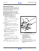
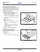
Secure Hoses
Refer to Figure 10
There are two or four hoses to clamp, requiring one or
two clamps. How to clamp them depends on the
available hardware. Figure 10 shows the recommended
stacking for four possible combinations.
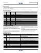
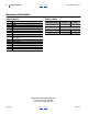
The clamp components are:
196-146D 3-HOSE CLAMP BRACKET
196-885D HOSE CLAMP HOLDDOWN
802-010C HHCS 5/16-18X1 1/4 GR5
802-172C HHCS 5/16-18X2 1/2 GR5
1/4 MARKER HYD HOSE GUARD
HOSE CLAMP BRACKET
HHCS 5/16-18X1 1/4 GR5
WASHER LOCK SPRING 5/16 PLT
WASHER FLAT 5/16 USS PLT
23. Clamp new and any existing hoses. If markers are
yet to be installed, place the upper clamp hardware
in preparation for marker hoses.
Closeout
24. If no additional hydraulic options are to be installed
at this time, bleed the Lift systems per the
instructions in the drill Operator Manual. Follow
hitching instructions carefully, due to high positive
and negative hitch loads in various drill
configurations.
25. Confirm selector valve handle(s) forward is
Transport, handle(s) aft is Field, and all Extend/
Retract settings operate Base/Rod cylinder ends as
expected.
Figure 10
Hose Clamp Combinations
27030
55
59
15
14
13
17
58
17
58
58
58
14
14
14
13
13
13
52
51
51
52
13
14
15
17
51
52
55
58
59