
Manual

MICRO HIGH POWER
ELECTRONIC SPEED CONTROLS W/BEC
The ElectriFly C-7 Nano and C-12 Micro ESC’s feature the “Safe Start”
system to prevent accidental motor starts by disabling the motor circuitry
until the throttle stick is moved to full throttle, then to the “off” position.
Other features include BEC circuitry which allows the motor battery to
power the receiver and servos. When the motor battery voltage is
reduced to .7 volts per cell on NiCd/NiMH and 2.8 volts per cell on LiPo,
the low voltage cut-off circuitry stops the motor while continuing to supply
power to the receiver and servos.This eliminates the need for and weight
of a separate receiver battery. Both ESC’s are programmable for use
with NiCd/NiMH or LiPo batteries. These ESC’s function with brushed
motors ONLY.
C-7 Nano C-12 Micro
Dimensions: 0.66" x 0.28" x 0.43" 0.83" x 0.31" x 0.43"
[17 x 7 x 11mm] [21 x 8 x 11mm]
Weight: 0.20 oz [5.5g] 0.28oz [8g]
Input Voltage: 6-8 cell NiCd/NiMH 6-8 cell NiCd/NiMH
2-3 cell LiPo 2-3 cell LiPo
Max Rated Current: 7 Amps 12 Amps
BEC Voltage: 5V/1 Amp 5V/1 Amp
Low Voltage Cutoff: 0.80V/cell NiCd/NiMH 0.80V/cell NiCd/NiMH
2.75V per cell LiPo 2.75V per cell LiPo
Connectors: Micro Plug Micro Plug
Switching Frequency: 2.5 kHz 2.5 kHz
Servos: 3 Micro Servos 3 Micro Servos or
4 Micro with good cooling
Read and follow these instructions carefully before using.
• Do not operate the airplane on or near water. Never allow water,
moisture or any foreign material onto the ESC’s PC board.
• Never use more cells then specified for the main battery pack.
• The ceramic capacitors must be properly installed on the motor to
prevent radio interference.
• Always disconnect the motor battery from the ESC when not in use.
• Always switch on the transmitter before switching on the ESC.
• Use heat shrink tubing to insulate any bare wires from the motor battery
to the ESC and from the ESC to the motor to prevent a short circuit.
• Allow the ESC to cool before touching.
The receiver plug attached to the speed control
plugs directly into a Futaba “J” receiver. However, if
you are using an Airtronics “Z”, Hitec “S” or JR
receiver, you will need to slightly modify the receiver
plug on the ESC. To modify the plug, use a hobby
knife or wire cutter to carefully cut off the alignment
tab on the side of the receiver plug as shown.
The white “signal wire” on the ESC receiver plug should be in the
same position in the receiver slot as the white wire on Futaba, the
blue wire on the new Airtronics “Z” connector, the yellow wire on the
Hitec “S” connector or the orange wire on the JR connector.
WARNING: This connector is NOT directly compatible with the old
Airtronics connector style. Use an Airtronics Servo Adapter to connect
this ESC to the older style Airtronics radios.
NEVER ALLOW THE BARE RED (+) AND BLACK (–) WIRES TO
TOUCH ON ANY RECEIVER OR ESC, AS PERMANENT DAMAGE
WILL RESULT TO BOTH ITEMS AND VOID ALL WARRANTIES.
Determine the best location for the ESC inside the fuselage.The ESC
should be in a position which allows good airflow for proper cooling,
and close enough to the motor so the motor wires reach the motor. It
is highly recommended to put cooling air intake holes in the front of
the fuselage and exit holes towards the aft end.
IMPORTANT: When using the ESC’s with the maximum number of
cells and servos, and at the maximum current draw, the ESC must
have good air flow over it to keep it cool.
The best method to mount the ESC in the fuselage is with Velcro
®
.If
the ESC will be mounted on wood, first saturate the wood with thin CA
and allow to dry. Cut a piece of Velcro (both hook and loop)
approximately 1/2" x 1". Attach the hook (hard) material to the inside
of the fuselage. Clean the bottom of the ESC (the side with the wires)
with rubbing alcohol and attach the loop (soft) material.
Motors generate radio noise which can interfere with your receiver
and cause problems. If your ESC seems to function erratically due to
motor noise, we recommend that you install two .01µF (103) non-
polarized, ceramic capacitors on the motor. These capacitors can help
reduce the radio noise generated by the motor and prevent possible
damage to the ESC.
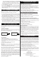
• Solder one of the leads from one of the
capacitors to the positive brush terminal
on the motor end cap.
• Solder of the leads from the second
capacitor to the negative brush terminal
on the motor end cap.
• Solder the remaining leads from both
capacitors to the side of the motor case.
Because of the many different types of plugs available, we cannot cover
the installation of each plug type.The following instructions will help you
prepare the wires for installation of any plug type. IMPORTANT: Make
sure the ESC is completely disconnected from input power.
1. Remove the existing plug by cutting the wires behind the plug, and
separate the red and black wires.
2. Strip 1/4" of insulation from the end of the red wire.
3. Twist the strands of the bare wires together tightly.
4. Tin the ends of the wires with solder made specifically for soldering
electronics. We recommend 60/40 rosin core solder.
A. Pre-heat your 15 to 30 watt soldering iron.
B.While holding the tip of the soldering iron on the bare wire, touch
the solder to the bare wire very near the iron tip and allow the liquid
STEP 4
CHANGING THE MOTOR &
BATTERY
PLUG (OPTIONAL)
STEP 3
INSTALLING MOTOR CAPACITORS
STEP 2
MOUNTING THE SPEED CONTROL
STEP 1
THE RECEIVER PLUG
IMPORTANT PRECAUTIONS
SPECIFICATIONS
INTRODUCING THE ELECTRIFLY
C-7 NANO
™
AND C-12 MICRO BRUSHED ESC’s
Trim Off
Solder to Side
of Motor
.01µF Capacitor (103)
Positive (+)
Brush
Terminal
Negative (-)
Brush Terminal