
Manual


13
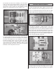
[2mm] drill bit. Center the elevator servo with your radio
system and install the servo arm onto the elevator servo as
shown. Mount the elevator servo next to the rudder servo
with a gap of approximately 1/4" [6mm] between the tips of
the servo arms. Leave enough room for the throttle servo.
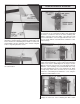
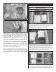
❏ 4. Thread a nylon clevis 20 complete turns onto a 36"
[914mm] pushrod. Slide a silicone clevis retainer onto the
clevis and connect the clevis to the third outer hole of the
rudder control horn. As you did with the aileron and fl ap
pushrods, use tape or a small clamp to hold the rudder in
the neutral position. Make a mark on the pushrod where it
crosses the outer hole in the servo arm. Make a 90° bend
at the mark on the pushrod and cut off the excess pushrod
1/4" [6mm] beyond the bend. Attach the pushrod to the servo
arm using a nylon FasLink. Thread the clevis up or down on
the pushrod as necessary to center the rudder with the servo
arm perpendicular to the servo case. When satisfi ed, slide the
silicone clevis retainer to the end of the clevis to secure it.
❏ 5. Install the elevator pushrod in the same manner. The
clevis on the elevator pushrod should attach to the outer hole
in the elevator control horn.
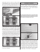
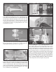
Glow Engine Installation
The Cherokee .40 ARF is designed to be fl own with a .40 to
.46 two-stroke glow engine, .56 four-stroke glow engine, or a
brushless out-runner motor. If you plan to install a brushless
motor, skip this section as it only contains information
relevant to installing a glow engine.
Note: This section shows photos of a two-stroke engine
being installed. The procedure for installing a four-stroke
engine is the same. Be sure to maintain the correct drive
washer distance as detailed in this section.
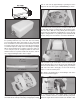
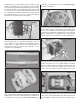
❏ 1. The fuel tank can be assembled as a two line system
consisting of a vent (pressure) line to the muffl er and a
carb line. Filling and emptying of the tank would need to be
done through the carb line, or an optional fuel fi ll valve (not
included). The tank can also be assembled as a three line
system having a vent line, carb line, and fi ll line. If installing
a fi ll line, puncture the top of the stopper above the sealed
off fuel tube hole. The fi ll and carb lines should extend out
1/2" [13mm] beyond the stopper and the vent line should
be bent upwards and left uncut. With the tubes installed in
the stopper, fi t the stopper plates loosely in place with the
3 x 25mm Phillips screw to hold the assembly together.