INSTRUCTION MANUAL WARRANTY Great Planes® Model Manufacturing Co. guarantees this kit to be free from defects in both material and workmanship at the date of purchase. This warranty does not cover any component parts damaged by use or modification. In no case shall Great Planes’ liability exceed the original cost of the purchased kit. Further, Great Planes reserves the right to change or modify this warranty without notice.
TABLE OF CONTENTS INTRODUCTION INTRODUCTION . . . . . . . . . . . . . . . . . . . . . . . . . . . . . . 2 Thank you for purchasing the Great Planes ARF Sport Floats. During our flight testing with these floats, we were amazed by the superb handling characteristics on the water and the ultra-smooth, realistic takeoffs and landings. PRECAUTIONS. . . . . . . . . . . . . . . . . . . . . . . . . . . . . . . 2 While the Great Planes ARF Sport Floats were designed for the .
Remember: Take your time and follow the instructions to end up with a well-built model that is straight and true. PREPARATIONS If you have not flown this type of model before, we recommend that you get the assistance of an experienced pilot in your R/C club for your first flights. You’ll learn faster and avoid risking your model before you are truly ready to fly it. Your local hobby shop has information about clubs in your area whose membership includes experienced pilots.
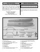
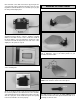
Parts Identification Important Building Notes Before starting to build, use the Parts Identification list to take an inventory of this kit to make sure it is complete, and inspect the parts to make sure they are of acceptable quality. If any parts are missing or are not of acceptable quality, or if you need assistance with assembly, contact Product Support. When reporting defective or missing parts, use the part names exactly as they are written in the Kit Contents list on this page.
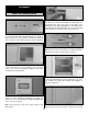
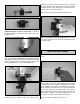
ASSEMBLY Install the Steering Servo ❏ 4. Clean any resin residue from the tray opening in the float. Trim any resin from the hardwood mounting rail inside the float. Put one of the 1/4" x 3/8" x 3-1/2" [6.4 x 9.5 x 89mm] basswood servo tray rails in the float, butting one end against the mounting rail. Mark the rear of the opening on the rail. Transfer the mark to the other rail as well. ❏ 1.
rails and make some shims from leftover ply. Tack glue the servo tray rails in place again and check the fit of the servo tray. When satisfied with the fit, use 6-minute epoxy to glue the rails permanently in place. Assemble the Water Rudder ❏ 8. Mount the servo to the 5/16" x 3/4" x 7/8" [8 x 19 x 22.2mm] basswood blocks, using the hardware supplied with the servo. Make sure the servo is oriented as shown in the photo with the servo arm pointing as shown.
making sure the water rudder and control horn are aligned as shown. Install a 2-56 x 3/8" [9.5mm] screw and 2-56 nut to hold the bracket to the rudder post. Use Great Planes Pro Threadlocker™ to hold the nut in place. Hint: Center punch the bracket before drilling the hole. ❏ 4. Assemble the Nylon rudder bearing, rudder post, aluminum bracket and nylon control horn as shown in the photo. Hold the control horn in place with a #2 x 3/16" [4.8mm] screw. ❏ 7.
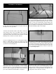
❏ 5. Insert the wire and rubber bushing into the hole you ❏ 2. Mount the water rudder assembly in the location shown in drilled in the transom. The rubber bushing is easier to insert if you stretch it on the wire as it is inserted. Use a screwdriver to carefully poke it through as needed. The rubber bushing is now inside the float. Secure the rubber bushing to the transom with some silicone rubber glue or medium CA. Insert the wire into the screw-lock connector. the above photo.
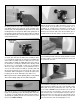
• For 60-size floats: Move the CG (Balance point) 1/2" ahead of the manufacturers recommended CG. • For 40-size floats: Move the CG (Balance point) 3/8" ahead of the manufacturers recommended CG. • For 20-size floats: Move the CG (Balance point) 9/32" ahead of the manufacturers recommended CG. ❏ 8. Cut a small notch in the servo hatch for the servo extension wire. Install a 12" servo extension wire on the servo lead. Secure the connection with tape, keeping the connection as water tight as possible.
PREPARE THE MODEL ❏ 3. If there is no rear mounting block, you must install one. ❏ 1. Install a 5mm wheel collar and set screw on each of the four ends of the float gear wires. The photo shows the two right ends of the gear wires. Remove the landing gear from your model. Place the float gear wires on the model and mark the location of the rear float wire. Note that we have reinstalled as many of the screws, etc. as we could, so as not to lose them and to seal the holes in the bottom of the fuselage.
❏ 6. This fuselage has a 1/8" [3.2mm] balsa side and a 1/8" ❏ 9. Using epoxy, glue the mounting block to the support [3.2mm] ply doubler. There is also a 1/4" x 1/4" [6.4 x 6.4mm] balsa filler stick glued to the bottom sheeting and resting on the edge of the ply doubler. Cut the stick and fuselage side down to the ply doubler. Do not cut deeper than 1/2" [12.7mm], the thickness of the mounting block. blocks, fuselage sides and former.
about 3/8" [9.5mm] from the sides of the floats. Drill 1/16" [1.6mm] pilot holes for the screws. ❏ 3. Waterproof the ply spacer assembly with some thin CA or paint. Install the ply spacer assembly in the front gear wire.This will prevent the forward float wire from moving in the groove. Secure the wire into place with the landing gear straps. ❏ 4. Remove all of the mounting screws from the fuselage and ❏ 2. Mount the floats to the float gear wires, making sure the right float is on the right side.
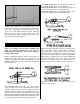
the stud about 13 turns into both the clevis and pushrod. Insert the inner pushrod into the outer pushrod tubing. ❏ 3. Use the small nylon tie straps to secure the servo extension wire to the float landing gear wires. Plug the servo extension wire into the “Y” connector from the receiver. IMPORTANT: Secure the connection with tape, keeping the connection as water tight as possible. Insert the connection into the fuselage so that it is entirely inside the fuselage.
pushrod 1/8" [3.2mm] from the rear of the float. Cut the inner and outer pushrods at the marked location. ❏ 6. Disconnect the pushrod clevis from the rudder control horn and pull the inner pushrod out a few inches. Cut the outer pushrod 3/8" [9.5mm] from the end (at the float end). Reconnect the clevis back to the control horn. ❏ 7. Thread the 2-56 x 6" [152mm] wire 13 turns into the inner pushrod. Insert the wire into the screw-lock connector on the water rudder control arm and cut the wire to length.
Note: Make sure the ventral fin is perpendicular to the bottom of the fuselage. ❏ 5. Remove the ventral fin assembly from the fuselage. Solidly glue the ventral fin to the mounting base. Balance the Model More than any other factor, the C.G. (balance point) can have the greatest effect on how a model flies, and may determine whether or not your first flight will be successful. If you value this model and wish to enjoy it for many flights, DO NOT OVERLOOK THIS IMPORTANT PROCEDURE.
Great Planes® Pro™ Adhesives Great Planes® Precision Z-Bend Pliers (GPMR8025) GPMR6002 Thin Pro CA 1 oz. GPMR6008 Medium Pro CA+ 1 oz. GPMR6045 Pro 6-Minute Epoxy 9 oz. High-quality Pro Adhesives provide model building’s best bonds...and a “Best If Used By” date on the label for visible proof of freshness! Thinformula Pro CA offers instant bonds, curing in just 1-3 seconds – it’s ideal for most assembly needs.