™ INSTRUCTION MANUAL SPECIFICATIONS Wingspan: 71.5 in [1815 mm] Wing Area: 836 in 2 [53.9 dm2] Wing Loading: 27−30 oz/ft 2 [82− 92 g /dm2 ] Weight: 9.75− 10.75 lb [4420 − 4870 g] Radio: 4–6 channel Engine: 1.20 cu in [20cc] 2-stroke glow, 1.55 cu in [25cc] 4-stroke glow, Rimfire 1.20 Brushless electric Length: 73 in [1855 mm] WARRANTY Great Planes Model Manufacturing ® Co. guarantees this kit to be free from defects in both material and workmanship at the date of purchase.
TABLE OF CONTENTS INTRODUCTION INTRODUCTION . . . . . . . . . . . . . . . . . . . . . . . . . . . . . . . . 2 SAFETY PRECAUTIONS . . . . . . . . . . . . . . . . . . . . . . . . . 3 ADDITIONAL ITEMS REQUIRED. . . . . . . . . . . . . . . . . . . 3 Engine Recommendations. . . . . . . . . . . . . . . . . . . . . . 3 Brushless Electric Motor . . . . . . . . . . . . . . . . . . . . . . . 3 Radio Equipment . . . . . . . . . . . . . . . . . . . . . . . . . . . . . 4 ADHESIVES, HARDWARE & OTHER ACCESSORIES. .
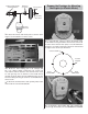
SAFETY PRECAUTIONS ADDITIONAL ITEMS REQUIRED Protect Your Model, Yourself & Others… Follow These Important Safety Precautions Engine Recommendations The glow engine sizes are straightforward and as printed 1. Your Sequence 1.20 ARF should not be considered a toy, on the cover. You cannot get any simpler than with the O.S. but rather a sophisticated, working model that functions very 1.20AX 2-stroke. If a 4-stroke is preferred, the O.S. 1.55FS-a much like a full-size airplane.
❍ Great Planes adhesive-back Velcro (GPMQ4480) Radio Equipment ❍ Electrifly Powermatch Power Meter Balancer (GPMM3220) The Sequence can be flown with as few as four channels, but the ailerons will have to be connected to the same channel in the receiver via a dual servo connector (FUTM4130 for Futaba) and the elevator servos will have to be connected to the same channel via a servo reverser (FUTM4150).
ORDERING REPLACEMENT PARTS Replacement parts for the Great Planes Sequence 1.20 ARF are available using the order numbers in the Replacement Parts List that follows. The fastest, most economical service can be provided by your hobby dealer or mail-order company. To locate a hobby dealer, visit the Great Planes web site at greatplanes.com. Choose “Where to Buy” at the upper right side of the page. Follow the instructions provided on the page to locate a U.S., Canadian or International dealer.
ASSEMBLE THE WINGS ❏ 4. Use thin CA followed by a small fillet of medium CA to reinforce the servo mounting blocks to the hatch covers. ❏ 1. Pull hard on the ailerons to test the hinges. Inspect the hinges to be sure enough glue has been used. Add a few ❏ 5. With the servos plugged in and the radio turned on, use drops of thin CA to any hinges that look dry. Note: CA “fogging” the plastic servo arm gauge to find the servo arms that will deposited on the covering can be cleaned with CA debonder.
NOTE: Every time wood screws are used throughout the rest of assembly always perform this procedure of installing and removing the screws, then hardening the holes with thin CA. ❏ 11. Cut and remove the covering from around the base of the horns. ❏ 12. Securely glue the horns in to position with CA. ❏ 8. Add a 6" [150mm] servo extension to each aileron servo. Secure the connections with 1-1/2" [40mm] pieces of the included heat shrink tubing as shown. Use a heat gun to shrink the tubing. ❏ 13.
Threaded Coupler 2-1/4" [57mm] ASSEMBLE THE FUSELAGE 4-40 Pushrod CAUTION: The turtledeck and fuselage bottom of the Sequence 1.20 are made from balsa-covered foam. Some solvents and adhesives will attack the foam, so use care—especially when using CA which will definitely “eat” into the foam. ❏ 15. Make the aileron pushrod from a 4-40 x 4-1/2" [115mm] pushrod cut to a length of 2-1/4" [57mm].
4-40x3/8" [10mm] Phillips and #4 Flat Washers #6 Washers (as spacers) Prepare the Fuselage for Mounting the Engine (or Electric Motor) 6-32" Set Screw 5-32" [4mm] Wheel Collar Fiberglass Wheel Pant ❏ 4. Mount the wheels and wheel pants as shown—don’t forget to use threadlocker on all the screws. ❏ 1. If using the O.S. 1.55 FS-a, remove the bottom cutout for the muffler. If using a brushless electric motor, remove all the other cutouts instead.
tick marks. If mounting the Great Planes Brushless Motor Mount for Large Motors drill the holes through the firewall at the four angled tick marks. If mounting the optional wood motor mount box, refer to the instructions on page 28 and assemble/mount the box as illustrated. Mount a Glow Engine Refer to this photo for the following two steps. ❏ 1. Temporarily mount the included engine mount to the firewall with four 8-32 x 1" [25mm] SHCS, #8 lock washers and flat washers.
Hook Up the Throttle Install the Fuel Tank ❏ 1. Refer to following photos to see which of the two throttle servo mounting locations will work best for your engine. Cut the side or bottom servo mount hole from the location you will use. ❏ 2. Connect a 12" [305mm] servo extension to your throttle servo and secure the connection with another piece of shrink tubing. ❏ 1. Prepare the stopper assembly as shown. Insert the stopper into the tank and tighten the screw.
Mount an Electric Motor Before mounting the motor and setting up the ESC and battery, read the following important battery precautions: IMPORTANT: If using multiple battery packs that are connected with an adapter, never charge the batteries together through the adapter. Always charge each battery pack separately.
from the collar on the end of the RimFire 1.20 motor shaft. Then, reinstall them with threadlocker and securely retighten. 11.1V (3-Cell) (3 PARALLEL adapter ter 7.4 V (2-Cell) NEVER connect battery packs with different Voltages in Parallel–only combine in Series. Otherwise, the batteries will try to “equalize” with the larger one trying to “charge” the smaller one, thus causing heat and likely a fire. Refer to this photo while mounting the motor and ESC. ❏ 3. Mount the motor to the mount.
SHCS, #8 lock washers and flat washers and threadlocker. How to Make an Externally-Accessible Arming Plug: ❏ 7. Before mounting the ESC consider the options for connecting the battery. First, the wires coming from the ESC are probably not long enough to reach the battery, so an extension of some sort may have to be made. And if using two 3S LiPo packs connected in series (as illustrated here in the manual), a Series Deans Ultra 2 to 1 Adapter (GPMM3143) will also be required.
❏ 8. Once you’ve made the arming plug, decide which of the three precut locations in the fuselage side you will use for mounting a Deans female Ultra Plug to serve as the receptacle. Solder the plug in-line between one of battery leads. Solder on any additional wire so the battery and ESC will reach. ❏ 9. Mount the ESC to the ESC mount with three #4 x 1/2" Phillips screws and #4 flat washers.
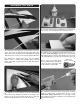
Cut the Cowl If going electric the cowl probably doesn’t need to be cut—just skip ahead to “Mount the Cowl” on page 18. But if using a glow engine the cowl must be cut to fit over the head and cylinder. If using an O.S. 1.55FS-a you’re in luck because we’ve provided a template that can be used as a guide. If installing a different engine you’ll have to figure out where to make the cut yourself.
❏ 5. Test fit the cowl and see where it needs to be cut next. Mark the inside again if necessary, or switch to a fine-point felt-pen to mark the outside. Remove the cowl and continue to cut in small increments. ❏ 6. Proceed slowly continuing to fit, mark and cut the cowl in small increments until you can get it over the engine— as you really “zero-in” on the cutout, switch to the sanding drum. When you’re really close, install the spinner back plate for aligning the front of the cowl.
Now let’s get back to the cowl ring… Mount the Cowl Now that you can get the cowl to fit over the engine it is time to determine how the cowl will be mounted. There are two options: You can use the standard wood screws from the outside, or use the optional cowl ring. Review the cowl fitting process to decide which way you prefer. The cowl ring requires fabrication of an extended ball-end hex driver, but the installation is “cleaner” and more durable as there will be no external screws.
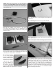
❏ 6. Once satisfied with the fit of the cowl ring, re mount it to the fuselage with the screws. ❏ 7. Use coarse sandpaper to roughen the cowl all the way around the inside so glue will adhere. “Prime” the inside of the cowl with a few squirts of CA accelerator to keep the CA from leaking around the cowl ring inadvertently gluing it to the fuselage. ❏ 4. Temporarily fasten the cowl ring to F-1 with four 4-40 x 1/2" [13mm] SHCS and flat washers—now you can test out your new extended hex driver! ❏ 8.
❏ 10. Medium CA will be used to glue the cowl to the cowl ❏ 14. Securely glue the back of the cowl ring with thin CA ring, but you’ll need an extended glue tip in order to reach down inside. Pipettes and Teflon tubing may be used, but we used a length of micro pushrod tubing fit over a CA tip. and the front of the cowl ring with medium CA. ❏ 11. Double-check that the cowl is positioned precisely as you want it viewing it from all angles to make sure.
METHOD 2: Mounting the Cowl with Wood Screws In the following steps it may be helpful to have an assistant drill the holes while you hold the cowl… Hard point Hard point ❏ D. Holding the cowl in position, use one of the templates ❏ A. If using wood screws to fasten the cowl, mark the screw hole locations over the hard points under the covering on both sides of the fuselage where shown. as a guide to drill the first 3/32" [2.4mm] hole through the cowl into the fuselage. ❏ E.
Finish the Cowl Hook Up the Rudder and Elevators ❏ 1. Same as was done with the ailerons, give a good pull on the rudder and look at the hinges to make sure they are all secure. Use thin CA to wet any hinges that look dry. ❏ 2. Making sure the trims and sub trims are centered, use your transmitter to center the rudder servo. ❏ 3. Enlarge the second-from-the-outer holes in a Great Planes 3" [150mm] double-side servo arm (GPMM1165) with a 7/64" [2.8mm] drill. Mount the servo arm to the servo.
❏ 10. place. Mount the rudder servo and hook up the rudder using the hardware shown—be certain to use threadlocker on all the 4-40 nuts and don’t forget to harden the servo mounting screw holes with thin CA. NOTE: Stand-offs are used under the ball links on the servo arm, but are not required on the rudder horn.
FINAL ASSEMBLY Set the C.G. Determine where the model balances before mounting the receiver battery. Then, mount the battery where required to achieve the correct C.G. ❏ 1. With the exception of the receiver battery, receiver and on/off switch, the Sequence should otherwise be in readyto-fly condition with everything else installed (including the motor battery positioned in the approximate location shown ❏ 4. Use a Great Planes C.G. Machine or lift the model with your fingers at the balance point.
Balance the Model Laterally PREFLIGHT ❏ 1. With the wing level, lift the model under the tail and by Identify Your Model the propeller shaft. Do this several times. Always attach your name, address, telephone number and AMA number somewhere on or inside your model. ❏ 2. If one wing always drops when you lift the model, it means that side is heavy. Balance the airplane by adding weight to the other wing tip.
APC 17 x 8E propeller powered by a 5,000mAh 6S battery draws about 80A, 1,750 Watts @ 7,500rpm (these are the initial, static/non-flying readings using a fully charged battery). And in-flight data from the ELogger shows that the average current draw throughout a normal flight is about 40A with the maximum current draw during full-throttle events about 72A. Once you run your motor on the ground you can compare your numbers to these as well as the current specifications for the motor.
Make all engine adjustments from behind the rotating propeller. 4) I will operate my model using only radio control frequencies currently allowed by the Federal Communications Commission. The engine gets hot! Do not touch it during or right after operation. Make sure fuel lines are in good condition so fuel will not leak onto a hot engine, causing a fire.
FLYING There are no particular flight characteristics about the Sequence 1.20 that you need to be made aware of ahead of time. The Sequence is a well-balanced, neutral flying plane that will go wherever you point it. Simply fly the Sequence within your capabilities and take it easy for the first couple of flights to give your self time to become acclimated to it. Have a ball! But always stay in control and fly in a safe manner. GOOD LUCK AND GREAT FLYING! 2.
to drill 1/16 " [1.6mm] pilot holes through the FRP motor mount plate. If using a different motor, mark, then drill holes to fit your motor. Hint: For perfection, fasten the template to the mount with 4-40 screws and nuts. 5/16" [8mm] 1/8" [3.2mm] 9/16" [15mm] 4. Glue the front bulkhead doubler and the side doublers to the assembly. 7. Remove the plywood template, then enlarge the pilot holes as illustrated for the RimFire 1.20. 5.
9. Mount your motor to the motor mount plate—the RimFire 1.20 uses four M3 x 8 screws. If also using the rear mount, fasten it into the mount assembly with four 4-40 x 3/8 " screws and washers. Test-mount the plate/motor assembly to the box with four 4-40 x 3/4" screws, washers and lock washers. Turn the motor by hand, making sure there is no interference and everything turns free and smooth. Make any adjustments necessary. Then, remove the mount plate/ motor assembly from the mounting box.
ENGINE CUTOUT TEMPLATE FOR O.S. 1.