
User Manual

NOTE: The rubber grommets are designed to absorb the
vibration energy from your engine. It is normal for them to
wear during usage. You should inspect the grommets for
excessive wear after the first five hours of operation and
every ten hours thereafter (more often if excessive wear is
noted). Replacement grommets are available at minimal
cost. You should replace the grommets when wear becomes
noticeable.
PREPARE THE ENGINE MOUNT:
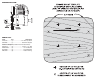
❏ 1. The 1/4" Birch Ply Mount has been designed for use
with a variety of models & engines. It may be necessary to
modify it for your particular application. For example, the
dashed lines on the upper corners of the enclosed template,
show where to cut off material to fit the Dynaflite
™
Super Cub
or Dynaflite Fly Baby.
❏ 2. Compare the Ply Mount with the side and top views of
the fuselage plan to determine if you will need to trim the
height or width of the mount, BUT DO NOT CUT IT YET.
❏ 3. Using the SIDE VIEW of the fuselage, place your
engine at the proper location and orientation. Be sure to align
the center of the crankshaft with the thrust line shown on the
plans. Place the Ply Mount against the back of the engine.
Move the Ply Mount up or down to obtain the best location
for mounting it to the fuselage. Mark the Ply Mount for the
vertical height of the engine mounting bolts. Also, mark the
location of the Ply Mount on the firewall.
❏ 4. Use the TOP VIEW of the fuselage to place your engine
at the proper location and orientation. Be sure to align the
center of the crankshaft with the thrust line shown on the
plans, noting any thrust angle. Place the Ply Mount against
the back of the engine. Move the Ply Mount left or right to
obtain the best location for mounting it to the fuselage. Mark
the Ply Mount for the horizontal location of the engine
mounting bolts. Also, mark the location of the Ply Mount on
the firewall.
❏ 5. Mark the center line locations of the holes to be drilled
for the engine mount bolts, BUT DO NOT DRILL THEM YET.
❏ 6. Determine how you will mount the Ply Mount to the
aircraft firewall, keeping in mind that the grommets will cause
the Ply Mount to be spaced 1/4" from the firewall. On Many
airplanes it will simply be a matter of bolting it directly to the
firewall with the supplied bolts. On others you may need to
build spacers onto the firewall. If you have not yet mounted
the firewall in the aircraft, you may be able to adjust it to
better fit the Ply Mount.
MOUNT THE ENGINE TO THE PLY MOUNT:
You are now ready to drill the engine mounting holes in the
Ply Mount. Remember the old carpenters saying: “Measure
twice, cut once”.
❏ 1. Drill 1/4" holes at the locations you marked for the
engine bolts.
❏ 2. Mount the engine to the Ply Mount using 1/4-20 x 1"
bolts and 1/4" flat washers (not supplied).
MOUNT THE ENGINE AND
PLY MOUNT TO THE FIREWALL:
You must now determine where to drill the holes for the
mounting bolts. When doing so, keep in mind the clearances
needed for the rubber grommets. If your mount comes with
pre-drilled holes, skip to Step 4.
❏ 1. Place the Engine/Ply Mount on the firewall using the
reference marks you made earlier. The Ply Mount will not fit
directly against the firewall as the engine mounting bolts are
on the rear of the Ply Mount.
❏ 2. Referring to the plans, double check the location again.
Determine the best location for the mounting bolts, then
mark the Ply Mount for the mounting bolts. Remember that
the rubber grommets will be mounted to the front and rear of
the Ply Mount and could conflict with parts of the engine.
Also keep in mind any parts of the airplane structure that
could conflict with the mounting bolts or blind nuts.
❏ 3. Drill 1/2" holes in the Ply Mount at the locations you
marked.
❏ 4. Install the eight rubber grommets in the Ply Mount.
Place the Engine/Ply Mount back on the firewall and mark
the location of the holes to be drilled in the firewall.
❏ 5. Drill 5/16" holes in the firewall at the locations you
marked. Install the 1/4-20 blind nuts in these holes.
NOTE: The engine bolt heads on the rear of the Ply Mount
will touch the firewall. Mark the firewall where the bolt heads
touch.
❏ 6. You will need to cut or drill clearance holes where the
engine bolts touched the firewall. Either partially drill into the
firewall with a 1/2" drill or use a Dremel
®
MultiPro
™
tool to
hollow out a clearance area.
❏ 7. Bolt the Engine/Ply Mount to the firewall using the 1/4-
20 x 1-1/4" bolts and 1/4" flat washers. If you had to install
spacers on the firewall, you may need to obtain longer bolts.
LARGE ENGINE
ISOLATION MOUNT
Assembly Instructions
Great Planes Model Manufacturing
3002 N Apollo Drive, Suite 1 Ph: (217) 398-8970, ext. 5
Champaign, IL 61822 Fax: (217) 398-7721
E-mail: airsupport@greatplanes.com
Web page: greatplanes.com
© 2014 V2.0
The Large Engine Isolation Mount
™
provides a simple
but effective way to mount your large gas or glow engine.
It is effective at dampening normal engine vibration,
which in turn will extend the life of both your airplane and
your radio system. It will also effectively reduce noise
due to vibration.
CAUTION: Proper balancing of your propeller is
essential. This engine mount system WILL NOT
compensate for an out of balance propeller. The rubber
grommets are designed to work under normal engine
vibration and will be quickly damaged under heavier
than normal vibration.
Printed In USAGPMG2000P01