
Manual


10
❏ ❏
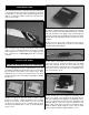
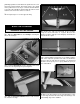
7. Slide the hinges into the slots in the elevator, sliding
the elevator tightly to the stabilizer. Apply six drops of thin
CA to each of the hinges. Allow the glue to harden. Do not
use CA accelerator on the hinges. This will cause the hinge
to get brittle and possibly crack.
❏ ❏
8. Thread a nylon clevis 20 complete turns onto each
36" [914mm] pushrod. Slide a silicone clevis retainer onto
each clevis and connect the clevis to the second hole from
the end of the control horn. Slide the pushrod wire into the
hole closest to the stabilizer on the right side of the fuselage.
Slide the wire into the fuselage until the control horn rests on
the plywood plate in the elevator. Drill 1/16" [1.6mm] holes
at the marks. Do not drill all the way through the elevator
halves! Thread a #2 x 3/8" [9.5mm] screw into each hole
and back it out. Apply a couple drops of thin CA glue to each
hole and let it harden. Attach the elevator control horn to the
elevator using four #2 x 3/8" [9.5mm] screws.
❏
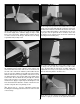
9. Repeat step 5 – 8 for the remaining elevator half,
installing the remaining pushrod into the hole on the left side
of the fuselage.
❏
10. Roughen the portion of the tail wheel wire assembly
that fi ts into the rudder with 220-grit sand paper and clean it
off with alcohol. Glue the tail wheel wire into the hole in the
LE of the rudder with medium or thick CA glue. Be sure not
to get glue onto the nylon tab where it rotates on the wire
(oil applied on the tail wheel wire around the tab will help
prevent glue from sticking to it).
❏
11. Place pins through the center of three hinges. Insert
the hinges into the slots in the rudder. Test fi t the rudder
to the fuselage with the tail wheel assembly. Make any
adjustments necessary so the nylon tab on the tail wheel
wire fi ts all the way into the slot in the fuse.
❏
12. Once you are satisfi ed everything fi ts, apply a light
amount of epoxy to each side of the nylon tab. Install the