
Manual


8
❏ ❏
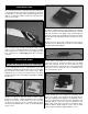
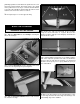
6. Inside the servo bay string is taped. Tie the string
to the servo lead. Taped to the root rib you will fi nd the other
end of the string. Pull the string and the servo lead through
the wing.
❏ ❏
7. Position the aileron servo hatch covers in place
and drill a 1/16" [1.6mm] hole through the mounting holes
and into the hatch mounting blocks. Thread a #2 x 3/8"
[9.5mm] screw into each hole and back it out. Apply a drop
of thin CA to each hole to harden the wood. Install the hatch
covers to the wings using four #2 x 3/8" [9.5mm] and four
#2 fl at washers.
❏
8. Thread a nylon clevis 20 complete turns onto each 6"
[152mm] pushrod. Slide a silicone clevis retainer onto each
clevis and connect the clevis to the outer hole of a nylon
control horn.
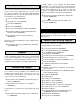
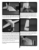
Refer to this photograph for steps 9-11
Hinge Line Hinge Line
CORRECT INCORRECT
Hi
❏
9. Position the control horns over the plywood plate
in the aileron (if you cannot see it, hold the aileron at a
shallow angle in good lighting or use a small pin to puncture
the covering) using the position of the servo arms as a
guide. Align the holes in the control horns directly over the
aileron hinge line and mark the location of the control horn
mounting holes.
❏ ❏
10. Drill 1/16" [1.6mm] holes at the marks you made
through the plywood plates. Do not drill all the way through
the ailerons! Thread a #2 x 3/8" [9.5mm] screw through
each hole and back it out. Apply a couple drops of thin CA
glue to each hole to harden the wood. When the glue has
dried, install the control horns onto the ailerons using two #2
x 3/8" [9.5mm] screws.
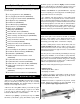
Servo Horn Pushrod Wire
90 Degree
Pushrod
Connector
❏ ❏
11. Use tape to hold the aileron in the neutral position.
Make a mark on the pushrod where they cross the outer
holes in the servo arms. Make a 90 degree bend at the
mark on the pushrod and cut off the excess pushrod 1/4"