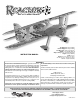
™ ARF .61-.91 SPORT BIPLANE Top Wingspan: 48 in [1220mm] Bottom Wingspan: 48 in [1220mm] 2 Total Wing Area: 1145 sq in [73.9 dm ] Weight: 7–7.5 lb [3170–3400 g] 2 Wing Loading: 14–15 oz/sq ft [43–46 g/dm ] Length: 58.5 in [1485mm] Radio: 4–5 ch. Engine: .61 cu in [10cc] two-stroke, .70–.91 cu in [11.5–15.0cc] four-stroke, RimFire™ .80 (50-55-500kV) INSTRUCTION MANUAL WARRANTY Great Planes® Model Manufacturing Co.
TABLE OF CONTENTS INTRODUCTION INTRODUCTION ............................................................... 2 SAFETY PRECAUTIONS ................................................. 3 DECISIONS YOU MUST MAKE ........................................ 3 Engine Recommendations ......................................... 3 Motor/Battery/ESC Recommendations ...................... 3 Radio/Servo Recommendations ................................ 4 ADDITIONAL ITEMS REQUIRED ....................................
DECISIONS YOU MUST MAKE PROTECT YOUR MODEL, YOURSELF & OTHERS...FOLLOW THESE IMPORTANT SAFETY PRECAUTIONS Engine Recommendations The recommended engine sizes for the Reactor .60 biplane are specified on the cover of this instruction manual. If you haven’t yet decided whether to go 2-stroke or 4-stroke, one big advantage of most 4-strokes (such as the O.S. Max .
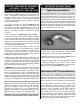
Following are the items illustrated in the instruction manual for equipping your Reactor .60 biplane with an electric motor: Another critically important component of the motor battery charging system is a cell balancer. LiPo battery technology is so powerful that each, individual cell within the battery pack should be charged equally—or balanced. Otherwise, capacity, power and the overall battery life will be diminished.
Here is some technical data for the suggested servos to assist you in making a decision: Torque (@ 4.8V) Weight Speed (sec./60° @ 4.8V) S9001 (FUTM0075) 54 oz-in [3.9 kg-cm] 1.7 oz [48g] .22 sec. S9650 (FUTM0260) 50 oz-in [3.6 kg-cm] .9 oz [26g] .14 sec. S3102* (FUTM0034) 51 oz-in [3.7 kg-cm] .7 oz [21g] .25 sec. *Ailerons only AILERON SERVO WIRE EXTENSIONS: Same as for the elevator and rudder servos, if using digital servos, be certain to use compatible servo extensions.
ADDITIONAL ITEMS REQUIRED BUILDING NOTES Adhesives and Building Supplies • The Reactor .60 biplane ARF is factory-covered with Top Flite® MonoKote® film. Should repairs ever be required, MonoKote can be patched with additional MonoKote purchased separately. MonoKote is packaged in six-foot rolls, but some hobby shops also sell it by the foot. If only a small piece of MonoKote is needed for a minor patch, perhaps a fellow modeler would give you some.
REPLACEMENT PARTS LIST KIT INSPECTION GPMA3340 ..... Fuselage GPMA3341 ..... Top Wing GPMA3342 ..... Bottom Wing GPMA3343 ..... Horizontal Stabilizer GPMA3344 ..... Rudder GPMA3345 ..... Cowl GPMA3346 ..... Landing Gear GPMA3347 ..... Wheelpants GPMA3348 ..... Canopy GPMA3349 ..... Struts GPMA3350 ..... Decals GPMA3351 ..... Battery Hatch GPMA3352 .....
PREPARATION ASSEMBLE THE FUSELAGE Test-Mount the Elevator and Rudder Servos It will be easier to cut the covering from the servo mounts and drill the servo mounting screws now, before the horizontal stabilizer is glued into position. ❏ 1. Use a covering iron with a cover sock to tighten the covering or remove any wrinkles found on parts of the model. Note: When moving the iron over trim pieces that are sharply pointed, be certain to move the iron away from the point, not toward it. ❏ 1.
Mount the Horizontal Stabilizer (Stab) ❏ 2. Test fit the servos in the servo openings in the fuselage. If using standard-size servos that don’t fit in the openings, use a fine-point felt-tip pen and the plywood servo cutout template as a guide to mark larger openings. Cut the enlarged openings along the lines you marked. ❏ 1. Use 30-minute epoxy to glue both 6 x 25mm bottom wing dowels into the bottom wing with 1/4" [6mm] protruding. ❏ 2.
B B' B = B' ❏ 7. Fold a piece of masking tape over the other end of the string end and mark a line on it. Pull the string to the tip of one side of the stab. Slide the tape along the string until the line on the tape aligns with the tip. Swing the string over to the same spot on the other side of the stab. If the mark on the tape doesn’t align, rotate the stab and slide the tape until both sides are the same and the stab is aligned. ❏ 5.
❏ 3. Join the matching elevator to the stab and take out the T-pins. Make sure there is a small hinge gap—just enough to see light through or to slip a piece of paper through. ❏ 10. Slide the stab into position, then partially out the other side, exposing the uncovered balsa on the other side of the stab. Apply more epoxy around the top and bottom of the stab, then slide it back into place.
Hook Up the Elevator and Rudder ❏ 1. Connect your servo extensions to the rudder and elevator servos. Secure the connectors with 1-1/2" [38mm] pieces of heat shrink tubing cut from the 3" [76mm] tubing supplied. Use a heat gun or a hobby torch to shrink the tubing. Refer to these photos while hooking up the elevator and rudder servos. ❏ 8. Use a small metal ruler or straightedge to work 30-minute epoxy down into the slot in the fuselage for the tail gear bearing.
We’re going to instruct you to center the servos and adjust the pushrods now, but this could be done later during final setup if you prefer. ❏ 3. Temporarily connect the servos to your receiver with a battery and a switch so you can move the servos with your transmitter. Turn on your transmitter and make sure the trims are centered and turn on the receiver. HOW TO SOLDER ❏ A. Use denatured alcohol or other solvent to thoroughly clean the pushrod.
Mount the Main Landing Gear ❏ 1. Use a 1/2" wrench and a 7/32" wrench (or crescent wrenches) to fasten a 5/32" x 1-1/4" [4mm x 32mm] bolt-on axle to each fiberglass main landing gear leg with a 5/16"-24 lock nut. ❏ 4. Mount the main landing gear to the fuselage with six 4-40 x 3/4" [19mm] SHCS and #4 lock washers and flat washers—use a drop or two of threadlocker on the threads of the screws. ❏ 2. Use a small metal file or a rotary tool with a reinforced cutoff wheel to grind a flat spot 1/8" [3.
BATTERY MOUNT PLATE 7" [178mm] “HOOK” SIDE 5-1/2" [140mm] “LOOP” SIDE 2" [51mm] OVERLAP ❏ 4. Test fit the battery and the mounting plate in the fuselage—note that the tabs in the front of the mounting plate key into the notches in the back of the firewall and that the sides of the mounting plate are locked into the former near the rear. (For clarity in the photo on the top, the battery strap has been removed so you can see how the battery plate fits.) ❏ 5.
Mount the Engine (A 4-stroke is shown in the photos, but the procedure for a 2-stroke is the same.) ❏ 1. Temporarily mount the included Great Planes .60-1.20 adjustable motor mount to the firewall with four 8-32 x 1" [25.4mm] SHCS and #8 flat washers and lock washers, but don’t tighten the bolts all the way yet. ❏ 7. Glue together the plywood ESC mount and glue the plywood screw doublers to the bottom of the mount. Mount the ESC to the mount with three #4 x 1/2" [12.7mm] screws and #4 flat washers. ❏ 2.
O.S. .61FX O.S. FS91 II, O.S. FS81 O.S. FS91 II PUMP ❏ 6. Before-mounting the engine, drill 3/16" [4.8mm] holes through the firewall at the crossmarks that align with the carburetor arm on your throttle as indicated in the sketch. If using a different engine, you may have to mark and drill the hole in a different location. ❏ 3. Glue both plywood fuel tank rings to the back of the firewall centered on the opening. HOOK RUBBER BANDS HERE ❏ 7. Bolt the engine to the engine mount with for 8-32 x 1" [25.
Hook Up the Throttle Refer to these photos and sketches while hooking up the throttle. GUIDE TUBE SUPPORTS SCREW-LOCK PUSHROD CONNECTOR 4-40 x 1/8" [3.2mm] SHCS (USE THREADLOCKER) 2-56 PUSHROD ❏ 1. Glue in the plywood throttle servo tray and hook up the throttle using the 36" [914mm] pushrod cut to length with a gray, plastic guide tube. Use a clevis on the carburetor end and a screw-lock connector on the servo end as shown.
❏ 1. Take an estimated measurement of where the engine head will protrude from the cowl. In this case the front of the cutout will be approximately 4-1/2" [115mm] from the back of the cowl. ❏ 4. Continue to fit, mark and cut the cowl as necessary until you can get it at least partially into position. As you proceed, try to keep the cutout as small as possible. Later, once the cowl has been mounted to the fuselage, the cutout will be trimmed to perfection. ❏ 2.
❏ 6. Make four templates with holes from thin cardstock to be used for marking the screw holes once the cowl is in position. Tape the templates to the fuselage with the holes in the templates aligned over the marks made in the previous step. ❏ 10. Remove the cardstock templates. Reposition the cowl and spinner. Holding the cowl in position, use the holes in the cowl as a guide for drilling four 3/32" [2.4mm] holes into the fuselage for the mounting screws. ❏ 11.
❏ 14. Cut any other holes in the cowl necessary for the needle valve, engine cooling, glow plug, etc. For the needle valve, it is convenient to use a paper template. ❏ 13. Same as when cutting holes for the engine, when cutting holes for the muffler, start small, test-fit the cowl, then continue to mark, cut and fit the cowl as necessary until you can get it into position. In the case of the O.S. .
❏ 2. Hold two servo mounting blocks to one of the aileron servos with pieces of thin cardstock between each block and the servo and under the servo—if using standard-size servos use two of the larger blocks, if using smaller servos like the 3102s use one of the smaller mounting blocks on the end of the servo that has the wire coming out of it. Drill 1/16" [1.6mm] holes into the blocks for the mounting screws. Here’s a photo of the finished cowl with all necessary cuts.
Refer to this photo while hooking up the ailerons. ❏ 7. Mount the hatches in the wing with #2 x 3/8" [9.5mm] button-head screws. This will require a .050" ballwrench, as mentioned in the front of this manual. ❏ 8. The same as was done for the elevators and rudder, make the pushrods and connect the bottom ailerons to the servos using the hardware shown. Don’t forget to use thin CA to harden the screw holes for the horn mounting screws and the hatch screws. ❏ 9.
1/16" [2mm] WING BOLT PLATE REMOVE THE COVERING 7/16" [11.1mm] 3/16" [4.8mm] ❏ 3. Remove the tabs. Apply 30-minute epoxy in the slots in the wing and to the tabs. Push the tabs into the slots. Wipe away any excess epoxy that squeezes out. Proceed immediately to the next step. ❏ 5. Cut the covering from one side of the plywood wing bolt plate as shown. ❏ 6. Bolt the bottom wing to the fuselage with the wing bolt plate.
❏ 10. Use 30-minute epoxy to glue the top wing dowels into the top wing. Wipe away any excess epoxy, then fit the wing brace over the dowels while the epoxy is hardening. Use care not to inadvertently glue the wing brace to the dowels or the wing. ❏ 7. Cut the covering from the bottom of the wing 1/16" [1.6mm] inside the line you marked and 1/16" [1.6mm] ahead of the wing trailing edge. Wipe away excess ink from the lines you drew with a few of your paper towel squares and denatured alcohol. ❏ 8.
RECOMMENDED STARTING BALANCE POINT 5-1/4" [133mm] FROM THE LEADING EDGE OF THE MIDDLE OF THE TOP WING Mark the Balance Point (C.G.) The balance point (C.G.) is to be marked on the bottom of the top wing. It will be easier to do this now, beforemounting the wing to the fuselage. This is where the model will be balanced during final setup later. C.G. RANGE TEMPLATE FORWARD MAXIMUM FORWARD BALANCE LIMIT RECOMMENDED BALANCE POINT (5-1/4" [133mm] FROM THE LE OF THE MIDDLE OF THE TOP WING) 4.
Final Radio Installation FINAL ASSEMBLY Refer to this photo while finishing the radio installation. Mount the Canopy ❏ 1.Wrap the receiver and receiver battery in 1/4" [6.4mm] R/C foam. Mount the battery and receiver to the plywood receiver/ battery tray inside the fuselage with straps made from the included hook-and-loop strips. If using a 2.
There are two ways to connect multiple battery packs: In Series and in Parallel. Now that the model is fully assembled and all of the external systems/components have been installed, access to the inside of the model will probably no longer be necessary. If you plan to transport your Reactor with the wings mounted, and if you are ready to install the wings at this time, go ahead and do so.
Set the Control Throws NO!! To ensure a successful first flight, set up your Reactor .60 biplane according to the control throws provided on page 31. The throws have been determined through flight testing and record-keeping allowing the model to perform in the manner in which it was intended. If, after you have become accustomed to the way the Reactor flies, you would like to change the throws to suit your taste, that is fine.
Proper Pushrod Hookup Avo i d i ng Flu t t e r, M axim i z ing S e rvo O u t p u t To rqu e Note: Your control horn may vary. When connecting pushrods and setting up your control CONTROL throws, it is critically SERVO ARM Pivot point HORN OFFSET OFFSET important to use proper pushrod geometry — that is the distance from the pushrod on the servo arm to the center of the output shaft (servo arm offset) compared to the distance from the pushrod on the control horn to the pivot point (control horn offset).
❏ 4. Measure and set the low rate elevator throws and the high and low rate throws for the rest of the control surfaces the same way. These are the recommended control surface throws: 3D RATE Up ELEVATOR Down HIGH RATE Up Down LOW RATE Up Down 2-3/4" 2-3/4" 1-3/8" 1-3/8" 7/8" 7/8" [70mm] [70mm] [35mm] [35mm] [22.2mm][22.2mm] 43° 43° 20° 20° 13° 13° Right Left Right Left Right Left ❏ 2. Glue the uprights to the sides, front and back.
❏ 3. If the tail drops, the model is “tail heavy.” The battery pack and/or receiver could be moved forward to get the model to balance, or weight could be added to the nose. If the nose drops, the model is “nose heavy” and the battery pack and/or receiver could be moved aft, or weight could be added to the tail.
• To stop a glow engine, cut off the fuel supply by closing off the fuel line or following the engine manufacturer’s recommendations. Do not use hands, fingers or any other body part to try to stop the engine. To stop a gasoline powered engine an on/off switch should be connected to the engine coil. Do not throw anything into the propeller of a running engine.
CHECK LIST FLYING During the last few moments of preparation your mind may be elsewhere anticipating the excitement of the first flight. Because of this, you may be more likely to overlook certain checks and procedures that should be performed before the model is flown. To help avoid this, a check list is provided to make sure these important areas are not overlooked. Many are covered in the instruction manual, so where appropriate, refer to the manual for complete instructions.
the throttle when at the correct altitude. Allow the nose to drop so the plane will maintain sufficient airspeed and simply bring the model in. If you’re coming in a little short, simply add throttle to stretch the landing. If coming in too hot, simply add power and try again. Flight If you’re a less-experienced modeler, your first priority will be to throttle back to reach a comfortable flying speed where the model will react somewhat slower than it would at fullthrottle.