
Manual

10
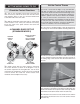
NOTE: The throws are measured at the widest part of the
elevators, rudder and ailerons. If your radio does not have
dual rates, we recommend setting the throws at the high
rate settings.
These are the recommended control surface throws:
ELEVATOR
LOW RATE
RUDDER
AILERONS
1"
[
25mm
]
17°
Up
1"
[
25mm
]
17°
Down
2-3/8"
[
60mm
]
24°
Right
2-3/8"
[
60mm
]
24°
Left
3/4"
[19mm]
12°
Up
3/4"
[19mm]
12°
Down
3D RATE
1-3/4"
[44mm]
31°
Up
1-3/4"
[44mm]
31°
Down
4-1/2"
[
114mm
]
52°
Right
4-1/2"
[
114mm
]
52°
Left
1-1/4"
[
32mm
]
20°
Up
1-1/4"
[
32mm
]
20°
Down
HIGH RATE
1-3/8"
[
35mm
]
24°
Up
1-3/8"
[
35mm
]
24°
Down
3-1/2"
[
89mm
]
37°
Right
3-1/2"
[
89mm
]
37°
Left
1"
[25mm]
16°
Up
1"
[25mm]
16°
Down
Balance the Model (C.G.)
More than any other factor, the C.G. (center of gravity/
balance point) can have the greatest effect on how a
model fl ies and could determine whether or not your fi rst
fl ight will be successful. If you value your model and wish
to enjoy it for many fl ights, DO NOT OVERLOOK THIS
IMPORTANT PROCEDURE. A model that is not properly
balanced may be unstable and possibly unfl yable.
Now is the time to install the propeller. At this stage the model
should be in ready-to-fl y condition with all of the components
in place including the complete radio system. The motor
battery has not been installed yet. You will move the motor
battery forward and aft to balance the plane.
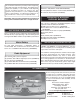
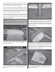
❏ 1. If using a Great Planes C.G. Machine
™
, set the rulers
to 4" [102mm]. If not using a C.G. Machine, use a fi ne-point
felt tip pen to mark lines on the top of wing, 1" [25mm] out
from the fuselage sides, on both sides of the fuselage 4"
[102mm] back from the leading edge. Apply narrow (1/16"
[2mm]) strips of tape over the lines so you will be able to feel
them when lifting the model with your fi ngers.
This is where your model should balance for the fi rst
fl ights. Later, you may experiment by shifting the C.G. 3/8”
[9.5mm] forward or 1/4” [6mm] back to change the fl ying
characteristics. Moving the C.G. forward will improve the
smoothness and stability, but the model will then be less
aerobatic (which may be fi ne for less-experienced pilots).
Moving the C.G. aft makes the model more maneuverable
and aerobatic for experienced pilots. In any case, start at
the recommended balance point and do not at any time
balance the model outside the specifi ed range.
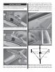
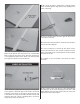
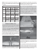
❏ 2. With the wing attached to the fuselage, all parts of the
model installed (ready to fl y), place the model upside-down
on a Great Planes CG Machine, or lift it upside down at the
balance point you marked. Place the motor battery on the
bottom of the fuselage.
❏ 3. If the tail drops, the model is “tail heavy.” Move the motor
battery forward to get the model to balance. If the nose drops,
the model is “nose heavy.” Move the motor battery aft. Once
you have determined the battery location required to balance
the plane note the location and where the battery would need
to be attached inside the fuselage, above the wing.