INSTRUCTION BOOK WARRANTY Great Planes Model Manufacturing Co., Inc. guarantees this kit to be free of defects in both material and workmanship at the date of purchase. This warranty does not cover any component parts damaged by use or modification. In no case shall Great Planes' liability exceed the original cost of the purchased kit. Further, Great Planes reserves the right to change or modify this warranty without notice.
TABLE OF CONTENTS INTRODUCTION...............................3 Precautions ......................................3 Abbreviations....................................4 English/Metric Conversions.............4 Types of Wood..................................4 Decisions You Must Make ................5 Other Items Required .......................6 Supplies and Tools Needed..............6 Die Patterns......................................7 Get Ready to Build ...........................8 TAILFEATHERS...............
WARNING! THIS IS NOT A TOY! THIS IS NOT A BEGINNER'S AIRPLANE! This R/C kit and the model you will build is not a toy! It is capable of serious bodily harm and property damage IT IS YOUR RESPONSIBILITY AND YOURS ALONE to build this kit correctly, properly install all R/C components and flying gear (engine, tank, pushrods, etc) and to test the model and fly it only with experienced, competent help, using common sense and in accordance with all safety standards as set down in the Academy of Model Aeronautics
slightly from the photos In those instances you should assume the plans and written instructions are correct Also you may notice a slight difference in length between some of the longer parts and the plans This is normal and is caused by the plans expanding and shrinking with the changing moisture content in the air Do not modify the parts to fit the plan.
DECISIONS YOU MUST MAKE NOW ENGINE, MOUNT, AND SPINNER SELECTION The recommended engine size range is as follows: 90 - 1 50 cubic inch displacement 2-cycle 1.20 -1.60 cubic inch displacement 4-cycle The complete "ENGINE APPLICATION TABLE" is printed on the fuselage plan reprinted here to help in your selection of engine, propeller, mount and spinner.
OTHER ITEMS REQUIRED SUPPLIES AND TOOLS NEEDED Four-channel radio with 6 servos (additional channel and retract servo required if retracts are being used). An 800 to 1200 mAh receiver battery is recommended (IMAA requires 1000 mAh) • 3 oz. Thin Bullet CA Adhesive • 3 oz. Medium or Thick Bullet CA Adhesive • 2.5 oz. 30-Minute Bullet Epoxy • 2 - Servo wire "Y"-harnesses. • Hand or Electric Drill • 2 - Servo wire extensions.
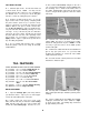
DIE PATTERNS Use This Drawing To Identify Die-Cut Parts 7
9" stick, cut the rudder bottom, and glue on the 1/4" x 1/4" x 3-1/2" balsa rudder top Cut two gussets from the remaining 1/4" x 1" balsa for the inside corners of the rudder Working right on the plan, pin these parts in place and glue them together to make the rudder framework. GET READY TO BUILD D 1.
BUILD THE FIN NOTE: You will construct the fin framework and add the 1/16" balsa sheeting, then, you will add the 3/8" balsa leading edge and fin top. D 1. Cut the remaining 1/4" x 3/4" balsa stick to make the fin trailing edge. D 2 Edge glue the two 1/4" x 3-1/4" x 1-1/2" balsa blocks together to make the 6-1/2" x 1-1/2" fin bottom Cut off the ends of this sheet to match the plan Pin the fin bottom and trailing edge to the plan.
D 8. Glue the 3/8" x 1" x 7" balsa fin top to the top edge of the fin assembly. Trim and sand the front end of this piece to match the plan. HINT: Using an X-acto knife, sharpen the inside of one end of a 1/8" diameter brass tube, and use it to cut the groove in the leading edge of the rudder.
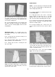
D 4 Using a sanding block and coarse (50 or 80-grit) sandpaper, sand both sides of the elevators to a taper as shown on the plans. The trailing edge should end up approximately 1/16" wide. (See photo proceeding page.
D (2) WBNT170 3/16" wire Main LG Struts CAUTION!!!: You must use extreme care when cutting hinge slots with an X-acto knife, to avoid cutting yourself! If the balsa part breaks while you are pushing on the knife, the blade could go into your hand before you know it! A good pre caution is to wear leather gloves while performing this step. (PARTS NEEDED FOR OPTIONAL RETRACTABLE LANDING GEAR) D (2) US10W16 1/4"x1-5/16"x3-5/16" Ply Rear Mtng. Plate D (2) US10W17 1/4"x3-5/16" Tapered Ply Front Mtng.
RIB D 2 Sand one end of each of the medium and short spars to a 2-1/2" taper as shown in the "Wing Spar Detail" on the plan DOUBLERS (Fixed Landing Gear - TAILDRAGGER) (Skip this section of you will be installing retracts) D 3. Glue the medium spars to the long spars, and glue the short spars to the medium spars, as shown in the "Wing Spar Detail." Sand the edges of the spars to remove any excess glue and to make the edges uniform. Make four spar assemblies.
LEADING & TRAILING EDGES D 3 The doubler for rib W-3 is marked for a long, narrow notch Extend the lines of this notch to the edge of the doubler, and cut out this notch D 1 The shaped and notched wing leading edges (LE) and trailing edges (TE) are fastened together by thin strips of balsa Separate them by cutting with an X-acto knife, as shown in the following sketch.
with the aft edge of the TE (see sketch below) You may cover the top edge of the Jig with a strip of waxed paper or plastic wrap to avoid gluing it to the TE space is limited, you may cut the left and right wing half drawings apart NOTE: Follow steps 2 through 45 to build the RIGHT wing panel, then repeat these steps to build the LEFT wing panel. D D 2 Pin one of the spars to the plan with the short spar facing up and toward the root.
D D 11. Lightly sand the tops of the ribs to blend with the notched trailing edge; then glue one of the 3/32" x 2" x 39-3/8" balsa trailing edge sheets in place. NOTE: The edge of the TE sheet may not be exactly straight, but just position the sheet so it slightly overlaps the TE, and any overlap can be sanded off later. This photo is not 100% accurate. Some components may vary. D D 8. Make sure the ribs are fully down on the plan and all ribs are inserted into the LE notches.
amount protruding on both ends of the wing Using thin CA, glue the front (beveled) edge of the leading edge sheeting to the back edge of the leading edge. Now wet the top surface of the sheeting (if necessary) to make it bend easier Apply thick CA glue to the top edge of the ribs and to the front half of the spar Then immediately bend the sheeting down onto the ribs and spar Hold the sheeting down with long strips of masking tape until the glue has set.
NOTE: Install a wheel on the strut and check out how much force it takes to raise the wheel If you are using standard (heavy) wheels, it may be necessary to increase the tension on the retract assist spring If you are using lighter wheels, such as Sullivan "Skylite" wheels, the stock spring tension may be adequate D D 29 Install the retract mechanism (with the gear strut but without a wheel) and the pushrod * Cut clearance holes and notches in the ribs and mounting plate as required for the strut and pushr
the TE sheeting, and it should extend about 1/8" past the ribs on each side to simulate cap strips Cut a hole in this sheeting over the servo rails just big enough for the servo to pass through, then mount the servo to the rails NOTE: For most standard servos, this will result in the top of the servo case being flush with the sheeting, with only a enough gap in the sheeting at each end of the servo for servo installation and access to the mounting screws.
drilling straight down through the aileron (not perpendicular to the top or bottom surfaces) Harden the balsa in the area of the control horns (on both sides of the aileron) by poking several small holes with a pin, then applying thin CA glue Sand smooth. Temporarily mount the nylon horn using the 2-56 x 5/8" machine screws and the nylon nutplates. D 46. Now go back and repeat Steps 2 through 45 to build the other wing panel. D D 42.
D 1. Place the two wing panels together on a flat surface and block up both wing tips 1-1/2". The blocks should be located at the W-13 ribs. Sand the root end of the wing panels until they fit together properly at that angle. D 2. With waxed paper or protective plastic under the center section, carefully align the wing panels at the centerline. Hold the leading and trailing edges together with pins or strips of masking tape. D 3. Lock the wing panels together by dripping thin CA into the center joint.
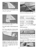
D 9. Sand the wing joint smooth all around. D 6 Using 30-minute epoxy, securely glue the dihedral brace to the back of the spars Observe (in the photograph) how two small balsa wedges were used to hold the dihedral brace against the spars with slight pressure Wipe off excess glue that may have squeezed out onto the top of the spar. Let the glue fully harden before proceeding.
D 1 Make location marks for the fiberglass reinforcement cloth, 2" each way from the wing centerline. Cut the 4" x 36" strip of glass cloth in half, making two strips approx. 18" long. D 8 After the glue has set, trim the excess cloth at the trailing edge with a sharp X-acto knife followed by a sanding block. D 9 Repeat the process for the other side.
Slightly round (or chamfer) the ends of the dowels that will protrude out of the LE INSTALL RETRACT SERVO (Skip this section if you are using fixed gear) D 6 Trial fit the dowels into the dowel holes You should be able to probe around and find the dowel holes in the dihedral brace Now trial fit the dowel plate over the dowels If the dowels fit too tightly, you may enlarge the holes slightly using a round file D 7.
FUSELAGE ASSEMBLY NOTE: For ease of working with these big plans, you may cut out the fuselage top and side views and work with them separately.
sufficient glue so it flows under the doubler to produce a strong bond D 11 From the 3/8" x 30" balsa triangle, cut pieces to fit between the tail wedge and the rear of F-4, along the bottom inside of both fuse sides. Glue in place. D 8. Find the 1-1/4" x 3" tapered balsa tail wedge. Holding the tail wedge in place on the right fuse side (aligned with the aft edge of the fuse side) draw a line on the fuse side at the front edge of the tail wedge.
correct size for the "A" firewall location (see Engine Application Table). If your engine requires the "B" or "C" firewall, it is necessary to cut the firewall down to the proper size Drawings for all three firewalls are shown on the fuse plan. Use these drawings to determine how much to cut NOTE: The top and bottom edges of F-1 are beveled at an 8-1/2 degree angle. When you cut your firewall, be sure to maintain the same angles on these edges Mark the "Front" and "Top" of F-1 for future reference.
D 5. Permanently attach the nose gear bearings (if applicable) to the back of the firewall with the 4-40 x 3/4" machine screws, cut off the excess bolt length that protrudes through the firewall, and trial fit the nose gear strut and steering arm. Temporarily mount your engine mount and engine onto the firewall, making sure everything fits properly. Remove the engine mount and the nose gear, leaving the nylon nose gear bearings in place.
the stab anchor block, and between the anchor block and the tail wedge (notice how the triangles are sanded to a taper near the aft end). Glue the triangles in place using the guidelines drawn in step 4, as shown in the photo.
D 8. Place the above assembly upside down on the waxed paper covered plan, and align the aft portion of the fuse with the plan. Begin pulling the fuse sides together, and pin the sides to the board every few inches as you work forward. Glue the fuse sides to the rear cross-brace, F-5, the front cross-brace, and F4 as you get to them. D 5. Accurately position the two pre-cut 1/4" x 1/2" balsa cross-braces on the plan, and pin them in place.
sanding as necessary for a good fit. Glue the holddown plate in place securely, using 30-minute epoxy. Then cut pieces of 3/8" hard balsa triangle and glue them in place above and below* the hold-down plate. Sand the triangles flush with the wing saddle. *You may wait to install the triangles under the hold-down plate until after you are able to turn the fuse right side UP. D 17.
INSTALL SERVOS AND PUSHROD GUIDE TUBES PARTS NEEDED: D (2) US1 0F09 1/4" x 1/2" x 4-3/8" Ply Servo Rails D (4) PLTB002 36" Plastic Outer Pushrod Guide Tube D (1) NYLON69 Nylon Nosegear Steering Arm D (1) SCRW007 6-32 x 1/4" Socket Head Cap Screw D (2) WIRES17 34" Steel Pushrod Wires D 4. Use an X-acto knife to sharpen one end of a piece of 3/16" (outside diameter) brass tubing.
strut from slipping under high stress steering arm and pushrod in place Leave the D 12 With the engine resting on the mount, plan the throttle pushrod routing The pushrod should be located as close as possible to the fuse side (to allow room for the fuel tank), and the guide tube should not have any tight bends Drill a 3/16" hole in F-1 for the throttle pushrod guide tube. D 13.
D 3 With the fuselage upside down on a flat surface, trial fit the wing into the wing saddle You may have to enlarge the holes in F-2 in one direction or another (using a round file), and you will probably have to sand the wing saddle a bit to allow the wing to seat properly. The wing should be centered, front to back, in the wing saddle area, with approximately equal spaces at the LE and TE. D 6.
FIT FUEL TANK and and fill lines The location of these holes will depend somewhat upon the type of engine you are using etc It is OK to drill the holes in the upper left and upper right corners, but we prefer drilling both holes in the upper right corner (as viewed from the rear) for easier access The holes must be located at least 5/8" in from the outside edge of the fuse side, to make room for the 1/2" balsa nose sides FUELPROOF TANK COMPARTMENT D 5 Now remove the engine mount and fuelproof the insid
D 2. Glue together the two halves of the 3/4" balsa chin block. Sand the glue joints smooth with your Tbar. D 6. If you're using trike gear, use a long 3/16" drill bit to drill down through the nose gear bearings and out through the chin block. Insert the nose gear strut and carve out enough of the chin block so that the axle is 5" from the surface of the chin block. D 3. Trial fit the chin block onto the bottom of the fuse, and cut off and sand the aft end of the chin block to match the angle of F-2A.
ASSEMBLE WING BELLY FAIRING PARTS NEEDED: D (2) US1 0W22 1/8" Die-cut Balsa Belly Fairing Sides D (1) US10F39 1/8" Die-cut Balsa Belly Fairing Formers D (2) US10W18 1/2" x 1-1/2" x 1-1/2" Balsa Fairing locks D (1) US 10W33 1 /8" x 3" x 24" Balsa Belly Fairing Sheeting D (1) US10W19 1/4" x 24" Balsa Triangle Sto D 3. Glue the die-cut 1/8" balsa front and rear belly fairing sides in position.
between the belly fairing sides and the bottom wing sheeting. INSTALL TURTLE DECK PARTS NEEDED: D (1) US10F27 1/8" Die-cut Ply Formers F-3A. F-4A and F-5A D (1) US1 0F34 1/8" Die-cut Balsa Former F-6A D (2) US10F11 1/4" x 1/4" x 31" Balsa Top Stringers D (2) US10F12 1/4" x 1/4" x 21" Balsa Side Stringers D (2) US1 0F13 3/32" x 3" x 33" Balsa Turtle Deck Sheeting D (1) US1 0F14 5/8" x 2-7/8" x 31" Balsa Top Block D 5.
D 3. Glue the 1/4" x 1/4" x 31" balsa top stringers and the 1/4" x 1/4" x 21" balsa side stringers to the formers HINT: If F-3A is slightly warped, you may straighten it during this step by twisting it straight while gluing the stringers Trim and sand the ends of the stringers flush with the front of F-3A and the rear of F6A.
NOTE: From now on, when working on the fuselage upside down, you should always support the fuselage in a protective stand, such as a Robart "Super Stand" to avoid dents and nicks. ASSEMBLE THE NOSE SECTION D 11 Using a long T-bar or sanding block with 80-grit sandpaper, sand the sheeting and stringers flush with the top edges of the formers.
D 6. Now center your spinner backplate over the spinner ring, and tack glue it to the 3/32" balsa spacers. D 9. Lay the top front block in place on top of the fuselage. The aft end of the block should be in the position shown on the plans (measure forward from F3A). Depending on your engine, you may also have to carve a groove for the needle valve. Cut and sand off the front of the top front block to mate with the spinner ring.
D 12 Remove the prop nut and propeller Pop the spinner backplate loose with a screwdriver and remove the spacers Remove the engine and mount in preparation for the next step, but mark the outline of the engine mount on F-1 with a pencil Photo shows SuperTigre 2500 engine with Supertigre muffler installed D 13.
with new #50 or #80-grit sandpaper for rough shaping The very coarse sandpaper is used to achieve the basic shapes Then use progressively finer grades of sandpaper for a smooth finish. D 4 After the rough sanding has been completed, temporarily re-mount your engine and slide on the spinner backplate You'll probably have to sand down the edges of the spinner ring for a good match with the spinner backplate.
nice fillets behind the little formers using lightweight filler. D 5. If you used lightweight filler to form the fillet, after sanding smooth you may spread a coat of thin CA over the surface of the filler, then give it a final sanding with 400 grit sandpaper This final coat is easy to sand smooth, and gives the filler a hard, durable surface to which covering sticks very well. D 3 You may build the fillet on top of the fillet base in one of the following ways.
D 5. Lay the stab in position on the stab saddle with the center point lined up with the tail end of the fuselage. If the stab protrudes beyond the end of the fuselage, sand a little off the front of the stab until it fits Carefully check the stab alignment by looking at the stab and wing from directly behind the fuse . ..
INSTALL SERVOS, HORNS AND PUSHRODS D 9 Carefully align the fin on the stab The fin must be positioned perpendicular to the stab and must line up with the fuselage centerline EXACTLY! Securely glue the fin in place with epoxy, doublechecking alignment while the glue sets D 1. Re-mount the aileron servos in the wing, and mount the nylon aileron horns. D 2. Screw the steel clevises (METAL013) approximately 2/3 of the way onto the threaded end of the two 12" steel wire pushrods (WIRES16). Steel Clevis D 10.
D 8 Mount the horns with 2-56 screws and the nylon nutplates which were attached to the horns CONTROL SURFACE THROWS NOTE: Throws are measured at the widest part of the elevator and rudder. 2-56 x 5/8" Machine Screw ELEVATOR*: (High Rate) D 9. Screw a metal clevis onto the threaded end of each long steel wire pushrod NOTE: Screw them on all the way until the threads are protruding inside the clevis.
curved "Lexan Scissors" (available from your hobby shop) is a very handy tool for trimming the canopy NOTE: The trim line on the canopy is approximate. Your canopy trim will vary, depending on how you sanded the fuselage It may be necessary to do some additional sanding of the fuse near the front of the canopy, if the canopy does not fit properly FINISHING ADDITIONAL FUELPROOFING If you have not already done so, make sure the entire engine compartment is completely fuelproof.
rounded tip, and follow the iron with a damp cloth, pressing the covering down. COVERING NOTE: Top Flite Super MonoKote was used to cover and trim the prototype models of the UltraSport 1000, and that is the recommended covering for this model.
2 Paint your pilot figure, and glue it to the cockpit floor NOTE: To avoid the possibility of the pilot coming loose inside the canopy, we recommend that you drill up through the cockpit floor and pilot base, and use two #6 or #8 sheet metal screws (not included) to lock the pilot in place.
3.
all the control surfaces do what they are supposed to. The engine operation must also be checked and the engine "broken in" on the ground by running the engine for at least two tanks of fuel Follow the engine manufacturer's recommendations for break-in. Check to make sure all screws remain tight, that the hinges are secure and that the prop is on tight •Use a low throttle setting when starting the engine.
climbing or diving a bit' The controls interact Yaw can be a r u d d e r p r o b l e m a lateral balance problem or an aileron rigging problem We must make many f l i g h t s w i t h minor changes between each.
be almost hands off Without touching any other control on the transmitter suddenly chop the throttle Did the nose drop? When you add power again, did the nose pitch up a bit? It so, you need some downthrust or nose weight When the thrust is correct the model should continue along the same flight path for at least a dozen plane lengths before gravity starts to naturally bring it down Do each maneuver several times, to make sure that you are getting a proper diagnosis Often a gust an accidental nudge on the c
TRIM FEATURE MANEUVERS OBSERVATIONS CORRECTIONS CONTROL CENTERING Fly general circles and random maneuvers Try for hands off straight and level flight Readjust linkages so that Tx trims are centered CONTROL THROWS Random maneuvers.
AMA SAFETY CODE IMAA SAFETY GUIDELINES As of September 15, 1989 (Portions reprinted as follows) Read and abide by the following Academy of Model Aeronautics Official Safety Code. For the purpose of the following IMAA Safety Guidelines, the term "Giant Scale" refers to a radio controlled model aircraft, either scale or non-scale, which has a wingspan of 80 inches or more for monoplanes, or 60 inches or more for multi-winged model aircraft, or, true quarter scale aircraft. GENERAL 1.
Fulfill all of your flying ambitions with our wide selection of world-class kits. Two of the easiest-flying, most acrobatic aircraft ever designed! • The kit quality and sparkling performance of the Ultra-Sport 1000 in .40- and .60-sized models. • Even if you're a veteran pilot, you'll be surprised at how much "better" your maneuvers look with an Ultra-Sport.
2-View Drawing Use This For Planning Your Trim Scheme 59