Change for life Installation & Owner's Manual Original Instructions Split Air Conditioner Models: CONS09HP230V1AF GEH(09)AA-D3DNA1C/I CONS12HP230V1AF GEH(12)AA-D3DNA1C/I CONS18HP230V1AF GEH(18)AA-D3DNA1C/I Thank you for choosing our product. Please read this Owner’s Manual carefully before operation and retain it for future reference. If you have lost the Owner's Manual, please contact your local distributor or visit www.greecomfort.com or send an email to info@twclimate.com for the electronic version.
Contents OPERATION INSTRUCTIONS 1. Part names and their functions ........................................................................................................... 1 2. How to use the remote control to operate the unit .............................................................................. 2 3. Maintenance ...................................................................................................................................... 7 4. Operating guide ........................
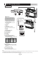
Part names and their functions OPERATION INSTRUCTIONS INDOOR UNIT 1 3 9 11 10 12 13 2 6 8 7 4 14 15 2 CAUTION Before opening the front panel, be sure to stop the operation and turn the breaker OFF. Do not touch the metal parts on the inside of the indoor unit, as it may result in injury. 1. Titanium Apatite Photocatalytic Air-Purifying Filter: ● These filters are attached to the inside 5 Air outlet selection switch • This setting blows air from upper outlet only.
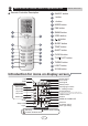
How to use the remote control to operate the unit Remote Controller Description OPERATION INSTRUCTIONS 1 ON/OFF button 2 - button 3 + button 4 MODE button 5 FAN button 6 SWING button 1 2 7 I FEEL button 3 8 4 button 9 SLEEP button 5 4 / 10 TEMP button 6 7 8 9 10 11 12 13 13 T-ON T-OFF button 16 14 TURBO button 14 14 11 QUIET button 12 CLOCK button 15 LIGHT button 15 16 X-FAN button Introduction for icons on display screen I feel Quiet Set fan speed Turbo mode Send signal Healt
How to use the remote control to operate the unit OPERATION INSTRUCTIONS Remote Controller Description 1 ON/OFF : Press this button to turn on the unit .Press this button again to turn off the unit. 2 Press this button to decrease set temperature. Holding it down above 2 seconds rapidly decreases set temperature. In AUTO mode, set temperature is not adjustable. 3 +: Press this button to increase set temperature.Holding it down above 2 seconds rapidly increases set temperature.
How to use the remote control to operate the unit 8 9 ● ● ● ● ● OPERATION INSTRUCTIONS / Press this button to achieve the on and off of healthy and scavenging functions in operation status. Press this button for the first time to start scavenging function; LCD displays“ ”. Press the button for the second time to start healthy and scavenging functions simultaneously; LCD displays“ ” and “ ” . Press this button for the third time to quit healthy and scavenging functions simultaneously.
How to use the remote control to operate the unit OPERATION INSTRUCTIONS 11 QUIET: Press this button, the Quiet status is under the Auto Quiet mode (display " " and "Auto" signal) and Quiet mode (display " " singal) and Quiet OFF (there is no signal of " " displayed), after powered on, the Quiet OFF is defaulted. Note: the Quiet function cannot be set up in Fan and Dry mode;Under the Quiet mode (Display " " signal), the fan speed is not available. 12 CLOCK: Press CLOCK button, blinking .
How to use the remote control to operate the unit OPERATION INSTRUCTIONS 18 Combination of "MODE " and "-" buttons : About switch between Fahrenheit and centigrade At unit OFF, press "MODE " and "- " buttons simultaneously to switch between ℃ and ℉ . 19 Combination of " TEMP " and "CLOCK" buttons : About Energy-saving Function Press “TEMP” and “CLOCK” simultaneously in COOL mode to start energy-saving function. Nixie tube on the remote controller displays “SE”. Repeat the operation to quit the function.
Maintenance OPERATION INSTRUCTIONS Before inspection and maintenance of the unit. PLEASE set power switch to “OFF” to cut off the power supply. 3.1 Units ● Indoor unit, Outdoor unit and Remote controller 1. Wipe them with dry soft cloth. ● Front panel 1. Open the front panel. Slide the two stoppers on the left and right sides inward until they click. 2. Remove the front panel. • Remove the string. • Allowing the front panel to fall forward will enable you to remove it. String 3.
Maintenance OPERATION INSTRUCTIONS Titanium Apatite Photocatalytic Air-Purifying Filter 4. Clean or replace each filter. See figure. 5. Set the air filter and Titanium Apatite Photocatalytic Air-Purifying Filter as they were and close the front panel. • Operation without air filters may result in troubles as dust will accumulate inside the indoor unit. 6. Wash the air filters with water or clean them with vacuum cleaner.
Maintenance OPERATION INSTRUCTIONS Check Check that the base, stand and other fittings of the outdoor unit are not decayed or corroded. Check that nothing blocks the air inlets and the outlets of the indoor unit and the outdoor unit. Check that the drain comes smoothly out of the drain hose during COOL or DRY operation. • If no drain water is seen, water may be leaking from the indoor unit. Stop operation and consult the service shop if this is the case. 3.4 Before a long idle period 1.
Operating guide OPERATION INSTRUCTIONS Working principle and special functions for cooling Principle: Air conditioner absorbs heat in the room and transmit to outdoor and discharged, so that indoor ambient temperature decreased, its cooling capacity will increase or decrease by outdoor ambient temperature.
Operating guide OPERATION INSTRUCTIONS 11
5 Precautions OPERATION INSTRUCTIONS 12
6 Checking before contact the service man PROBLEM CAUSES 13 OPERATION INSTRUCTIONS
Installation of indoor unit INSTALLATION INSTRUCTIONS SELECTION OF INSTALLATION LOCATION. CAUTIONS FOR INSTALLATION WHERE ● Such a place where cool air can be distributed AIR CONDITIONER TROUBLEIS LIABLE throughout the room. TOOCCUR. ● Such a place where condensation water is easily ● Where there is too much of oil area. drained out. ● Where it is acid base area. ● Such a place that can handle the weight of indoor unit. ● Where there is irregular electrical supply.
Installation of indoor unit INSTALLATION INSTRUCTIONS Refrigerant piping 1)Drill a hole ( 55mm in diameter ) in the spot indicated by the symbol in the illustration as below . 2)The location of the hole is different depending on which side of the pipe is taken out . 3)For piping ,see Connecting the refrigerant pipe ,under Indoor Unit Installation(1). 4)Allow space around the pipe for a easier indoor unit pipe connection.
Installation of indoor unit INSTALLATION INSTRUCTIONS Boring a wall hole and installing wall embedded pipe For walls containing metal frame or metal board ,be sure to use a wall embedded Inside pipe and wall cover in the feed-through hole to prevent water leakage. Wall embedded pipe Be sure to caulk the gaps around the pipes with caulking material to prevent (field supply) water leakage. 1)Bore a feed-through hole of 55mm in the wall so it has a down slope toward the Wall hole cover outside.
Installation of indoor unit INSTALLATION INSTRUCTIONS 3 tabs Installing indoor unit 1.Preparation Casing Open the front panel, remove the 4 screws and dismount the front grille while pulling it forward. Front grille Follow the arrows to disengage the clasps on the front case to remove it. Front panel Follow the procedure below when removing the slit Remove front grille portions. For Moldings Remove 4 screws Open the front panel Remove the pillars.
Installation of indoor unit INSTALLATION INSTRUCTIONS The mounting plate should be installed on a wall which can support the weight of the indoor unit. 1) Temporarily secure the mounting plate to the wall, make sure that the panel is completely level, and mark the boring points on the wall. 2) Secure the mounting plate to the wall with screws.
Installation of indoor unit INSTALLATION INSTRUCTIONS Connecting the refrigerant pipe 1)Use torque wrenches when tightening the flare nuts to prevent damage to the flare nuts and gas leaks. Open-end wrench (fixed) Coat here with refrigeration oil Flare nut Wrench Connection pipe Indoor unit tubing 2)Align the centres of both flares and tighten the flares and tighten the flare nuts 3 or 4 turns by hand. Then tighten them fully with the torque wrenches.
Installation of indoor unit INSTALLATION INSTRUCTIONS Checking for gas leakage 1)Check for leakage of gas after air purging 2)See the sections on air purges and gas leak checks in the installation manual for the outdoor unit. Check for leakage here Apply soapy water and check carefully for leaking gas. wipe soapy water off after the check is complete. Attaching the connection pipe Attach the pipe after checking for gas leakage, described above.
Installation of indoor unit INSTALLATION INSTRUCTIONS Live the sensor securing plate, remove the front metal plate cover, and connect the branch wiring to the terminal block. 1)Strip wire ends (15mm) 2)Mach wire colours with terminal numbers on indoor and outdoor unit’s terminal blocks and firmly screw wires to the corresponding terminals. 3)Connect the earth wires to the corresponding terminals. 4)Pull wires to make sure that they are securely latches up, then retain wires with wire retainer.
Routine check after installation INSTALLATION INSTRUCTIONS Check after installation Items to be checked Possible malfunction Has it been fixed firmly? The unit may drop,shake or emit noise. Have you done the refrigerant leakage test? It may cause insufficient refrigerating capacity. Is heat insulation sufficient? It may cause condensation and dripping. Does the unit drain well? It may cause condensation and dripping.
9 Configuration of connection pipe and additional volume of refrigerant INSTALLATION INSTRUCTIONS 1. Standard length of connection pipe 5m、7.5m、8m 2. Min length of connection pipe For the unit with standard connection pipe of 5m, there is no limitation for the min length of connection pipe. For the unit with standard connection pipe of 7.5m and 8m, the min length of connection pipe is 3m. 3.
Configuration of connection pipe and additional volume of refrigerant INSTALLATION INSTRUCTIONS Sheet 2. Additional refrigerant charging amount for R22 R407C R410A and R134a Diameter of connection pipe mm Liquid pipe Gas pipe Indoor unit throttle Outdoor unit throttle Cooling only, Cooling only Cooling and cooling and heating (g / m) heating (g / (g / m) m) Ф6 Ф9.5 or Ф12 20 15 20 Ф6 or Ф9.5 Ф16 or Ф19 50 15 50 Ф12 Ф19 or Ф22.2 100 30 120 Ф16 Ф25.4 or Ф31.
GREE ELECTRIC APPLIANCES, INC. OF ZHUHAI Add: West Jinji Rd, Qianshan, Zhuhai,Guangdong, China, 519070 Tel: (+86-756) 8522218 Fax: (+86-756) 8669426 E-mail: gree@gree.com.cn www.gree.