PACKAGED TERMINAL AIR CONDITIONER/HEAT PUMP INSTALLATION/OWNER’S MANUAL
Thank you for choosing an ETAC II Packaged Terminal Air Conditioner & Heating Unit! You can feel confident in your selection because the same pride in craftsmanship and engineering knowledge that goes into millions of other Gree installed products worldwide has gone into your unit. Please read this owner’s manual carefully before operation and retain it for future reference. Table of Contents Safety Considerations . . . . . . . . . . . . . . . . . . . . . . . . . . . . . . . . . . . . 2 Nomenclature . . .
SAFETY CONSIDERATIONS WARNING Please read the following before installation or use. CAUTION WARNING Recognize safety information. This is the safety-alert symbol. When you see this symbol on the unit and in the instructions or manuals, be alert to the potential for personal injury. Understand these signal words: DANGER, WARNING, and CAUTION. These words are used with the safety-alert symbol. DANGER – identifies the most serious hazards which will result in severe personal injury or death.
NOMENCLATURE GENERAL Gree packaged terminal air conditioners and heat pumps provide a high standard of quality in performance, workmanship, durability and appearance as they heat and cool the occupied air space year round. This manual provides information for ease of installation, operation and maintenance. All models are designed for through-the-wall installation. Separate installation instructions are included with all accessory components.
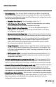
UNIT FEATURES This ETAC II has many exciting features which are different than those found on standard PTAC models. The owner must be familiar with these features in order to fully understand the operation and capability of the unit. • Intelligence – Your ETAC II unit has an on board computer that utilizes real time diagnostics to prolong the life of your unit.
UNIT FEATURES • Unit Configuration – There are many different configuration possibilities, through both dip switches and the digital keypad, that allow you to configure the unit for your exact application. See section on unit configuration for more details. The following are the configuration selections that have not previously been mentioned: • Fahrenheit °F or Celsius °C – The unit can display in either °F or °C.
UNIT FEATURES • LED Indicators and Buttons – The touch pad has buttons for MODE, FAN SPEED, ON/OFF, SETPOINT UP and SETPOINT DOWN. It also has LEDs that correspond to the mode, fan speed and setpoint operation, to indicate the unit’s status. The LEDs below the mode button, FAN, COOL, and HEAT, indicate what operating mode is active. The LEDs below the Fan button, Low, Hi and Auto, indicate the fan speed that is selected. The LED located in the lower right corner is the unit On/Off status LED.
ELECTRICAL DATA WARNING CAUTION WARNING WARNING ELECTRICAL SHOCK HAZARD – Failure to follow this warning could result in personal injury or death and/or property damage. DO NOT use an extension cord. POWER CONNECTION OPTIONS The appropriate power cord accessory kit is determined by the voltage, and amperage of the branch circuit. The unit does not come with a power cord (or hard wire kit). An accessory power cord kit must be installed on the unit.
ELECTRICAL DATA Table 1 – SUGGESTED BRANCH CIRCUIT WIRE SIZES* Nameplate Amps AWG Wire Size † 7.0 to 12 12.1 to 16 16.1 to 24 14 12 10 LEGEND AWG – American Wire Gauge * Single circuit main power wire from electrical panel to unit. AWG based on 240VAC Single Phase, 100 ft. distance 1-way, max. 5% allowable voltage drop. GROUNDING For safety and protection, the unit is grounded through the power cord plug or through separate ground wire provided on hard wired units.
INSTALLATION WARNING CAUTION WARNING CAUTION PROPER INSTALLATION IS THE RESPONSIBILITY OF THE INSTALLER. Product failure due to improper installation is not covered under the limited Product Warranty. CHASSIS INSTALLATION Units are shipped without a sleeve. In applications where unit is a replacement, it is recommended that a standard wall sleeve be used. These units can retrofit Carrier, General Electric, Amana, Trane, and Friedrich sleeves/grilles (be sure outdoor grille is installed on the sleeve).
INSTALLATION Coil Tube Sheets Fig.
INSTALLATION RETROFIT SLEEVE PREPARATION IMPORTANT: Inspect wall sleeve thoroughly prior to installation. Manufacturer does not assume responsibility for costs or damages due to defects in sleeve or WARNING for improper installation. CAUTION WARNING WARNING ELECTRICAL SHOCK HAZARD – Failure to follow this warning could result in personal injury or death. Disconnect all power to unit to avoid possible electrical shock during installation. Fig. 4 – GE Plastic Sleeve Remove bottom seal from plastic sleeve.
INSTALLATION CHASSIS AND POWER CORD INSTALLATION PREPARATION 1. Carefully remove shipping tape from the front panel. 2. Remove front panel. a. Pull out at the bottom to release it from the tabs (1). b. Then lift up (2). Junction Box Cover SHIPPING TAPE Unit Connec REMOVE SHIPPING SCREW IF PRESENT 2 Junction Box 1 Fig. 6 Fig. 7 4. Connect power cord connector to unit connector. 3. Remove junction box. a. Remove junction box cover by removing three screws from front (save these for later). a.
INSTALLATION 5. Re-install junction box and cover. Secure power cord. a. Re-install junction box. b. Use wire clamp to secure power cord to basepan with screw provided. c. Replace junction box cover. Fig. 10 Wire WireClamp clamp 6. Lift unit level and slide into wall sleeve until seal rests firmly against front of wall sleeve. a. Secure with 4 mounting screws provided with the unit. b. Careful not to over tighten and strip the screws. Wire clamp Fig. 11 Power Supply Cord 7. Replace front panel. a.
SYSTEM CONFIGURATION VENTILATION CONTROL The unique ventilation system is activated by a two position control. Fresh outside air is redirected by the vent door to the indoor room. A polymer air filter prevents dirt and debris from entering the room from outdoors. The ventilation control lever is located at WARNING left side of unit, behind the front panel. REMOVE SHIPPING SCREW IF PRESENT Fig.
SYSTEM CONFIGURATION DIGITAL CONTROL USER INPUT CONFIGURATION The adjustable control dip switches are located at the lower portion of the control box. The inputs are only visible and accessible with the front cover removed from the PTAC. Fig. 17 – Dip Switch Location Location of Dip Switches on Unit DIP SWITCH SETTING • Emergency Heat Override – Switch 1 In the unlikely event of a compressor failure a heat pump unit maybe switched to operate in only the electric heat mode until repairs can be made.
SYSTEM CONFIGURATION DIP SWITCH CONFIGURATION Fig. 18 – Dip Switches UP DOWN Freeze Guard Setpoint Limit 1 Setpoint Limit 2 Fan CON/CYC for cooling Fan CON/CYC for heating Wall Thermostat Enable Electric Heat Only (for heat pumps) Table 4 – Dip Switch Functions No.
SYSTEM CONFIGURATION KEYPAD CONFIGURATION Additional unit configurations are available using the keypad. • To Enter Configuration Mode Apply power to unit. Within 30 seconds press and hold the Fan Speed and Setpoint Down button for 5 seconds. • To scroll through the Keypad Configuration options Press and release the Fan Speed button. The stored value will be displayed. • To modify Configuration settings Press and release the Setpoint Up or Setpoint Down buttons.
SYSTEM CONFIGURATION WALL THERMOSTAT INSTALLATION ETAC II heat pump and heat/cool models will work with WARNING most common 24vac single stage wall thermostats. CAUTION WARNING CAUTION ELECTRICAL SHOCK HAZARD – The unit and accessories should be installed and serviced only by trained, qualified installers and service technicians. Thermostat Wire Routing (under sleeve, behind front panel) 1. Disconnect all electrical power to unit including disconnecting plug, fuses and circuit breakers. Fig.
SYSTEM CONFIGURATION WALL THERMOSTAT INSTALLATION (CON’T) 7. Connect thermostat wire to the ETAC II thermostat connection terminals per wire diagram (see Fig. 22). NOTES: 1. Use terminal “O” for heat pump connection only. 2. Terminal “C” (common) is typically only required for digital thermostats. NOTES: Any illegal input combinations will be captured as thermostat wiring failures and will light the STATUS LED indicator on main board (see Intelligent Self-Checking Control section). Fig.
SYSTEM CONFIGURATION ENERGY MANAGEMENT INPUT (FRONT DESK CONTROL) The ETAC II can interface to a switch signal from remote energy management input, called EM signal or front desk control. The input signal must be 24 VAC. If unit receives a 24 VAC signal, it will turn off; otherwise, the unit runs normally. This function will be disabled under Freeze Guard protection. See Fig. 21 for terminal connections.
OPERATION Fig. 24 – ETAC II Display and Touchpad ABOUT THE CONTROLS ON YOUR UNIT NOTE: After power failure, unit automatically restores last programmed settings. 1. ON and OFF MODES ON MODE – Places unit in ready or operation mode. OFF MODE – Places unit in standby mode. NOTE: The LED above the ON/OFF button will be green when unit is ON and red when the unit is OFF. All other LEDs will be off when unit is set to OFF mode. Power remains connected to unit. 2.
CARE AND CLEANING Preventive maintenance is essential to proper unit operation, efficiency and longevity, and required to maintain equipment warranty. To ensure equipment operates properly, it must be properly maintained. Equipment operation should be checked and verified several times during each year. For typical unit inspection and maintenance, follow the guidelines below: FRONT PANEL AND CASE Turn unit off and disconnect power supply. To clean, use water and a mild detergent.
ll up CARE AND CLEANING Coils Coils Coils Grille Grille Grille AIR FILTERS IMPORTANT: Turn unit off before cleaning. IDENTIFYING CLOGGED FILTER The most important thing you can do to maintain unit efficiency is to clean the filters at least every 30 days (or sooner depending on application). Clogged filters reduce cooling, heating and airflow. Dirty filterNeeds cleaning Keeping filters clean will: • Decrease cost of operation. • Save energy. • Prevent clogged indoor coil.
TROUBLESHOOTING POSSIBLE CAUSES UNIT DOES NOT START • Unit may have become unplugged • Fuse may have blown • Circuit breaker may have been tripped • Unit may be off or in wall thermostat mode. Check section on dip switch settings to verify dip switches are set properly. • Unit may be in a protection or diagnostic failure mode. See section on Intelligent Self-checking Control. UNIT NOT COOLING/HEATING ROOM • Unit air discharge section is blocked • Temperature setting is not high or low enough.
TROUBLESHOOTING POSSIBLE CAUSES SOLUTIONS WATER DRIPPING INSIDE • Wall sleeve is not installed level • Clogged drain • Wall sleeve must be installed with a 1/4 bubble pitch toward the outside for proper drainage of condensation. Check that installation is level and make any necessary adjustments. • The condensate drain may be partially or fully plugged. ICE OR FROST FORMS ON INDOOR COIL • Low outdoor temperature • Dirty filters • When outdoor temperature is approximately 55°F (12.
GREE ELECTRIC APPLIANCES, INC. www.greecomfort.com LIMITED WARRANTY TWO-YEAR PARTS AND LABOR LIMITED WARRANTY – During the first two years after purchase, GREE will, through its authorized independent servicing dealer or service stations*, and free of charge to the user or subsequent users, repair or replace any parts that fail due to defect in material or workmanship. The replacement part can be a new or remanufactured part as provided at GREE’S sole option.