
Instructions / Assembly
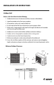


OUTDOOR UNIT INSTALLATION
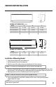
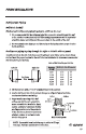
Outdoor Unit Dimensions
35
13 3/16
27 9/16
15 5/16
38
14 5/16
22
16 13/16
3
31 1/8
36 1/41
39 3/8
24
15 9/16
14 9/16
1
13
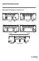
30K and 36K 230V
18K and 24K 230V
Outdoor Unit
Indoor Unit
Wires
Red
White
Black
Green
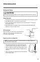
POWER AND WIRING INSTALLATION
Indoor Unit Wire Connections
Disconnect all electrical power to indoor and outdoor units including disconnects,
fuses and circuit breakers. Lockout and tag all disconnect switches.
1. Open front cover of indoor unit and remove field wiring terminal block cover.
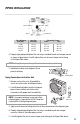
2. Pull interconnecting wires up from back of indoor unit and position in close to the
terminal block on indoor unit.
NOTE: Record wire colors and terminal references for uses with Outdoor Unit wire connections.
3. Connect wiring to indoor unit per system wiring diagram.
NOTE: The indoor unit is powered from the outdoor unit, depending on local code,
a disconnect switch may need to be installed to a power supply circuit.
4. Replace field wiring cover and close front cover of indoor unit.
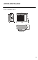
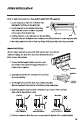
Indoor Disconnect Switch ( If required)
Local codes may require a disconnect switch within sight of the indoor unit. Use a DFS
Disconnect Switch Accessory Kit (Part No: DFS-SWITCH-A) to break wires going to the
N(1), 2, 3, terminals on the indoor unit, as shown in the wiring diagram below:
20
WARNING
Indoor Unit
Disconnect Switch
Wires
Outdoor Unit
Red
White
Black
Green
TWD-1673 Livv+ install printer_rev.qxp_Layout 1 1/3/17 5:29 PM Page 29