
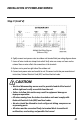
Installation Guide


Indoor Ambient Temp. Sensor F1 Short/Open of the Indoor Ambient Temperature Sensor
Indoor Evaporator Temp Sensor F2 Short/Open of the Indoor Evaporator Temperature Sensor
Outdoor Ambient Temp Sensor F3 Short/Open of the Outdoor Ambient temp Sensor
Outdoor Coil Temp Sensor F4 Short/Open of the condenser coil Temperature Sensor
Outdoor Discharge Air Temp Sensor F5 Short/Open of the Outdoor Discharge Temperature Sensor
Liquid Valve Inlet Temp Sensor b5 Short/Open of the liquid valve Temperature Sensor
Suction/Gas Valve Outlet Temp Sensor b7 Short/Open of the gas valve Temperature Sensor
Indoor Configuration Jumper C5 Missing Configuration Jumper on Indoor Control Board
High Discharge Temp Protection E4 Compressor Discharge high Temperature Protection
High Current Protection E5 Power Supp
ly is not Stable and Voltage Range is too Large
Communication Error E6 Mis-wired or Communication Failure between the Indoor and Outdoor units
Overload Protection E8 Overload Protection
Compressor Overheat Protection H3 Compressor Thermal Overload Protection
IPM Protection H5 Module Current Protection(namely IPM Protection)
Indoor fan Malfunction H6 Indoor Fan Stopped or Running too Slow
Motor De
synchronizing H7 Compressor Desynchronizing
PFC Error Hc PFC Protection
Startup Failure Lc Compressor Startup Failure
Phase Loss Ld Compressor phase Failure/Reverse Protection
Indoor/Outdoor Mismatch LP Indoor and Outdoor Units Unmatched (Model or Capacity)
Compressor Current Protection P5 Phase Over-Current Protection
Radiator Temp Sensor Error P7 Short/Open Circuit of the Module Temperature Sensor
Radiator Overheat Protection P8 Module Temperature Protection
4-Way Valve Malfunction U7 Bad Connection, Solenoid Failure or Valve Malfunction
Troubleshooting
This unit has onboard diagnostics. Informational and error codes will be displayed on the LED display on the
front panel of the indoor unit in place of the temperature display. The unit will provide informational codes
to alert the user of special system operations. Informational codes are not signs of system malfunctions or
failures. The following is a list of system informational codes and descriptions:
TROUBLESHOOTING
Error codes are an indicator of a system malfunction or failure. The following list of error codes and descriptions:
Possible CausesError CodesEquipment Fault
Possible CausesInfo CodeDescription
Mode Conflict E7 Some Indoor Units are Requesting Heat and Some cooling.
Defrosting H1 Defrosting Indoor Coil during Heating Mode
27 28
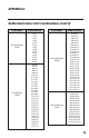
APPENDIX A
Authorized Indoor Unit Combinations
18,000 BtuH Indoor Unit Size
Dual Configuration 9K+9K
2 Zones 9K+12K
24,000 BtuH Indoor Unit Size
9K+9K
9K+12K
9K+9K
9K+12K
9K+18K
12K+12K
12K+18K
18K+18K
9K+9K+9K
9K+12K+12K
9K+9K+12K
9K+9K+18K
12K+12K+12K
Dual Configuration
2 Zones
Tri-Configuration
3 Zones
30,000 BtuH Indoor Unit Size
9+9
9+12
12+12
9+18
12+18
18+18
9+9+9
9+9+12
9+12+12
9+9+18
12+12+12
9+12+18
12+12+18
9+9+9+9
9+9+9+12
9+9+12+12
Dual Configuration
2 Zones
Tri-Configuration
3 Zones
Quad-Configuration
4 Zones
30,000 BtuH Indoor Unit Size
9+9
9+12
9+18
9+21
9+24
12+12
12+18
12+21
12+24
18+18
18+21
18+24
21+21
21+24
24+24
9+9+9
9+9+12
9+9+18
9+9+21
9+9+24
9+12+12
9+12+18
9+12+21
9+12+24
9+18+18
9+18+21
9+18+24
9+21+21
12+12+12
12+12+18
12+12+21
12+12+24
12+18+18
12+18+21
18+18+18
9+9+9+9
9+9+9+12
9+9+9+18
9+9+9+21
9+9+9+24
9+9+12+12
9+9+12+18
9+9+12+21
9+9+18+18
9+12+12+12
9+12+12+18
12+12+12+12
Dual Configuration
2 Zones
Tri-Configuration
3 Zones
Quad-Configuration
4 Zones
TWD-0813-017 Multi install rev:Layout 1 9/27/13 12:53 PM Page 29
High Pressure Protection E1 Too much refrigerant or High Ambient conditions or low airflow.