
Installation Guide


INSTALLATION OF REFRIGERANT PIPING
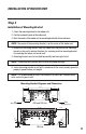
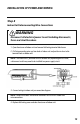
Step 7
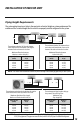
Piping Connections to Outdoor Unit
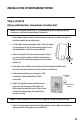
1. Remove service valve cover (if provided) to access
the service valves and refrigerant ports. The outdoor
unit refrigerant port sizes may vary. See System
Requirement Section for refrigerant port sizes.
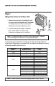
2. Carefully bend and adjust length of refrigerant
pipes to meet outdoor unit service valves
connections with proper tools to avoid kinks.
NOTE: Use proper techniques to cut and re-flare refrigerant pipes, if required.
An R410A Flaring Tool is required for re-flaring refrigerant pipes.
Service
Valve Cover
INSTALLATION OF REFRIGERANT PIPING
3. Apply a small amount of refrigerant oil to the flare connection on the refrigerant pipe.
4. Properly align piping and tighten flare nut using a standard wrench and a torque
wrench as shown in the indoor piping section.
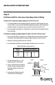
5. Carefully tighten flare nuts to correct torque level referring to the following Torque Table:
NOTE: Over tightening may damage flare connections and cause leaks.
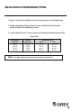
Pipe Diameter Nut Size
Tightening Torque
inch (mm) inch (mm) ft-lbs N-m
1/4 (6.35) 1/4 (17) 10 to 13 14 to 18
3/8 (9.5) 3/8 (22) 25 to 30 34 to 42
1/2 (12.7) 1/2 (25) 36 to 45 49 to 61
5/8 (15.9) 5/8 (29) 50 to 60 68 to 82
Torque Table
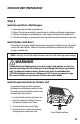
Capacity Size Quantity of
Tube Size
(BTUH) Adapters Provided (Inch)
18,000 0 None
24,000 2 3/8 to 1/2
30,000 2 3/8 to 1/2
1 1/4 to 3/8
1 1/2 to 3/8
36,000 1 1/2 to 5/8
1 3/8 to 1/4
1 5/8 to 3/8
2 3/8 to 1/2
2 1/4 to 3/8
2 1/2 to 3/8
2 1/2 to 5/8
42,000 1 3/8 to 1/4
1 5/8 to 3/8
1 3/8 to 1/2
1 5/8 to 1/2
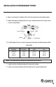
An adapter pipe may be required to transition from the indoor unit to the outdoor unit
refrigerant port. Piping adapters are provided with some models. See table below for factory
provided piping adapter quantity and size:
NOTE: In some situations, field fabricated piping adapters may be required.
17 18
TWD-0813-017 Multi install rev:Layout 1 9/27/13 12:53 PM Page 19