DUCTLESS INVERTER HEAT PUMP INSTALLATION MANUAL Models: NEO09HP115V1A NEO12HP115V1A NEO09HP230V1A NEO12HP230V1A NEO18HP230V1A NEO24HP230V1A NEO30HP230V1A NEO36HP230V1A
Thank you for choosing a Gree Neo Ductless Heat Pump for your customer. Please read this installation manual carefully before installing and starting up the Neo System. Take a moment to fill out the product and installation form on the back cover. Retain both the manual and installation record for future reference.
SAFETY PRECAUTIONS Please read the following before installation. Recognize safety information. This is the safety-alert symbol. When you see this symbol on the unit and in instructions or manuals, be alert to the potential for personal injury. Understand these signal words: DANGER, WARNING, and CAUTION. These words are used with the safety-alert symbol. DANGER identifies the most serious hazards which will result in severe personal injury or death.
SAFETY PRECAUTIONS CAUTION • The unit should be installed and serviced only by trained, qualified installers and service mechanics. Untrained personnel can perform basic maintenance functions such as cleaning coils. All other operations should be performed by trained service personnel. • Owner should be cautioned that children should not play with the appliance. WARNING ELECTRICAL SHOCK HAZARD Failure to follow this warning could result in personal injury or death.
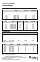
SYSTEM REQUIREMENTS Piping Requirements PIPE SIZE in (mm) Unit Size (BtuH) Voltage Liquid Line Suction/Gas Line 9,000 12,000 9,000 12,000 18,000 24,000 30,000 36,000 115v - 1ph 60hz 115v - 1ph 60hz 208/230v - 1ph 60hz 208/230v - 1ph 60hz 208/230v - 1ph 60hz 208/230v - 1ph 60hz 208/230v - 1ph 60hz 208/230v - 1ph 60hz 1/4 (6) 1/4 (6) 1/4 (6) 1/4 (6) 1/4 (6) 1/4 (6) 1/4 (6) 1/4 (6) 3/8 (9.5) 3/8 (9.5) 3/8 (9.5) 3/8 (9.
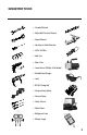
SUGGESTED TOOLS • Standard Wrench • Adjustable/Crescent Wrench • Torque Wrench • Hex Keys or Allen Wrenches • Drill & Drill Bits • Hole Saw • Pipe Cutter • Screw drivers (Phillips & Flat blade) • Manifold and Gauges • Level • R410A Flaring Tool • Clamp on Amp Meter • Vacuum Pump • Safety Glasses • Work Gloves • Refrigerant Scale • Micron Gauge 5
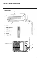
INSTALLATION SITE INSTRUCTIONS Step 1 Installation Site of Indoor Unit Select a site that allows for the following: • Ensure the installation complies with the installation minimum dimensions and meets the minimum and maximum connecting piping length and maximum change in elevation. • Air inlet and outlet will be clear of obstructions, ensuring proper airflow throughout the room. • Condensate can be easily and safely drained. • All connections can be easily made to outdoor unit.
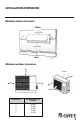
INSTALLATION DIMENSIONS Indoor unit 2 3 4 Part Name 1. 2. 3. 4. 5. 6. 7. 8.
INSTALLATION DIMENSIONS Minimum indoor clearances Ceiling 6 in (0.15m) 5 in (0.13m) 5 in (0.13m) 6 ft (1.
INSTALLATION OF INDOOR UNIT Step 2 Installation of Mounting Bracket 1. Attach the mounting bracket to the indoor unit. 2. Find the horizontal center of the indoor unit. 3. Mark the center of the indoor unit on mounting bracket for future reference. NOTE: The center of the mounting bracket is not the center of the indoor unit. 4. Remove the mounting brackets from the indoor unit and position the mounting bracket on the wall in desired location.
INSTALLATION OF INDOOR UNIT Mounting Bracket Diagrams and Dimensions Wall Wall 6 3/4 21 3/8 5 1/8 5 1/8 Φ2 1/8 27 3/8 2 7 5/8 2 1/8 Φ 8 1/ 1 3/4 Φ2 Right (Rear piping hole) 09K and 12K Unit 11 3/4 3 1/8 5 5/8 Left (Rear piping hole) 1 5/8 1 5/8 Φ2 1/8 1/2 4 3/4 18K Unit 5 1/2 7 1/4 12 3/8 27 Φ2 3/4 29 3/8 29 3/8 9 3/4 9 3/4 1/8 4 1/8 2 4 4 1 5/8 2 Φ 11 1/4 11 1/4Φ2 Φ 3/ 2 4 3/ 4 3/ 2 Φ 4 3/ 13 1/8 13 1/8 1 5/8 2 2 1/2 12 3/4 24K Unit 12 3/4 3 1/2
INSTALLATION OF INDOOR UNIT Step 3 Drill Hole in Wall for Interconnecting Piping, Drain & Wiring If indoor unit refrigerant piping is going to exit from the rear: 1. It is recommended that the refrigerant pipe flare connectors extend through the wall to the outside. In some situations field-fabricated piping extensions will be required to extend the indoor unit refrigerant flare connections to the outside of the wall. 2.
OUTDOOR UNIT PREPARATION Step 4 Install Ground Pad or Wall Hangers 1. 2. 3. 4. Determine proper location for outdoor unit. Follow all instructions provided by manufacturer for installing wall hangers or ground pad. Verify the wall hangers or ground pad can safely support the weight of the outdoor unit. Verify the wall hangers or ground pad is level and meets all outdoor dimensional clearances.
INSTALLATION OF REFRIGERANT PIPING Step 5 Piping Connections to Outdoor Unit CAUTION Use refrigeration grade tubing ONLY. No other type of tubing may be used. Use of other types of tubing will void manufacturer’s warranty. Make sure there is enough piping to cover the required length between the outdoor and indoor unit. Piping Preparation • Do not open service valves or remove protective caps from tubing ends until all connections are made. • Keep tubing free of dirt, sand, moisture and contaminants.
INSTALLATION OF REFRIGERANT PIPING 4. Open front cover of indoor unit and remove field wiring terminal block cover. Route the interconnecting wires to terminal block in control box. Field Wiring Cover 5. Allow interconnecting wires to hang free. Wire connections will be handled later in these instructions. 6. Adjust the length of condensate drain hose to easily meet the drain pipe of the indoor unit. Make connection and secure with a hose clamp.
INSTALLATION OF REFRIGERANT PIPING Step 6 Piping Connections to Outdoor Unit 1. Remove service valve cover (if provided) to access the service valves and refrigerant ports. 2. Carefully bend and adjust length of refrigerant pipes to meet outdoor unit service valves connections with proper tools to avoid kinks. Service Valve Cover NOTE: Use proper techniques to cut and re-flare refrigerant pipes, if required. An R410A Flaring Tool is required for re-flaring refrigerant pipes. 3.
INSTALLATION OF POWER AND WIRING Step 7 Indoor Unit Interconnecting Wire Connections WARNING Disconnect all electrical power to unit including disconnects, fuses and circuit breakers. 1. Open front cover of indoor unit and remove field wiring terminal block cover. 2. Pull interconnecting wires up from back of indoor unit and position in close to the terminal block on indoor unit.
INSTALLATION OF POWER AND WIRING Step 8 Outdoor Unit Wire Connections WARNING Disconnect all electrical power to unit including disconnects, fuses and circuit breakers. 1. Remove the service panel on right side of the outdoor unit. Cable Cross Board 2. Insert interconnecting wires and main power wires through the wire holes on conduit mounting bracket. 3. Secure main power conduit (and interconnecting wire conduit, if required) with locking nuts to conduit mounting bracket. Wire Hole 4.
INSTALLATION OF POWER AND WIRING 5. Following the same wire colors and terminal references from the indoor unit, tightly connect interconnecting wires to the outdoor unit terminal block per wiring diagram above. NOTE: Crossing interconnecting wires will cause system malfunction and possible damage. 6. Tightly connect main power wires to outdoor unit terminal block per wiring diagram above. 7. Secure all wires inside wire clamp/strain relief.
VACUUM TESTING Step 9 Leaking Test 1. Connect the charging hose of the manifold valve to charge the end of the low-pressure valve. 2. Add dry nitrogen to a pressure of 200 lbs. Tightly close both high- and low-pressure valves. 3. Leak-test flare fittings with soap bubbles. If no leak is detected, release nitrogen. Step 10 System Vacuum and Charge CAUTION UNIT DAMAGE HAZARD Never use the system compressor as a vacuum pump. It may result in equipment damage or improper system operation.
VACUUM TESTING 5. Evacuate using either deep vacuum or triple evacuation method. 6. After evacuation is complete, fully close the low side of manifold gage and stop operation of vacuum pump. 7. The factory charge contained in the outdoor unit is good for up to 25 ft. (8 m) of line length. NOTE: For refrigerant lines longer than 25 ft (8 m), add add’l refrigerant per foot of extra piping up to the maximum allowable length. See System Requirement section on page 4 for more info 8.
START-UP Step 11 Fig. a Installing Photocatalytic Filter (optional) 1. Lift front panel and remove air filter. (Fig. a). 2. Attach photocatalytic filter onto air filter. (Fig. b). 3. Install air filter as shown; close panel. (Fig. c). Fig. b Air Filter Photocatalytic Filter Fig. c Step 12 Start-up and Checkout Test Operation Perform test operation after completing gas leak and electrical safety check. 1. Turn on electrical disconnect to outdoor unit. 2.
START-UP AND TROUBLESHOOTING Explain Following Items To Customer With The Aid Of The Owner’s Manual: 1. How to turn system on and off; selecting COOLING, HEATING and other operating modes; setting a desired temperature; setting the timer to automatically start and stop system operation; and all other features of the Remote Control and display panel. 2. How to remove and clean the air filter. 3. How to set air with the swing louvers. 4. Explain care and maintenance. 5.
GREE ELECTRIC APPLIANCES, INC. www.greecomfort.com PRODUCT & INSTALLATION RECORD For your convenience, please record the model and serial numbers of your new equipment in the spaces provided. This information, along with the installation data and dealer contact information, will be helpful should your system require maintenance or service. UNIT INFORMATION Model No. Serial No.