WALL MOUNT DUCTLESS AIR CONDITIONING & HEATING SYSTEM INSTALLATION MANUAL Models: SAP09HP230V1A SAP12HP230V1A SAP18HP230V1A SAP24HP230V1A
Thank you for choosing a Sapphire Wall Mount Unit for your customer. Please read this installation manual carefully before installing and starting up the Sapphire System. Take a moment to fill out the product and installation form on the back cover. Retain both the manual and installation record for future reference. Table of Contents Safety Precautions . . . . . . . . . . . . . . . . . . . . . . . . . . . . . . . . . . . . . . . . . . . 2-3 Nomenclature . . . . . . . . . . . . . . . . . . . . . . . . . .
SAFETY PRECAUTIONS Please read the following before operation. Recognize safety information. This is the safety-alert symbol. When you see this symbol on the unit and in instructions or manuals, be alert to the potential for personal injury. Understand these signal words: DANGER, WARNING, and CAUTION. These words are used with the safety-alert symbol. DANGER identifies the most serious hazards which will result in severe personal injury or death.
SAFETY PRECAUTIONS WARNING • The unit should be installed and serviced only by trained, qualified installers and service technicians. Untrained personnel can perform basic maintenance functions such as cleaning coils. All other operations should be performed by trained service personnel. • Owner should be cautioned that children should not play with the appliance. WARNING ELECTRICAL SHOCK HAZARD Failure to follow this warning could result in personal injury or death.
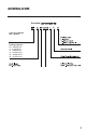
NOMENCLATURE Example: SAP12HP230V1AO SAP A Series Designation SAP - Sapphire Cooling Capacity 09 - 9,000 BTUH 12 - 12,000 BTUH 18 - 18,000 BTUH 24 - 24,000 BTUH 30 - 30,000 BTUH 36 - 36,000 BTUH 4
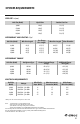
SYSTEM REQUIREMENTS PIPE SIZE in (mm) Unit Size (ButH) Liquid Line Suction/Gas Line 9,000 12,000 18,000 24,000 1/4 (6) 1/4 (6) 1/4 (6) 1/4 (6) 1/2 (12) 1/2 (12) 5/8 (15) 5/8 (15) REFRIGERANT LINE LENGTHS ft (m) Unit Size (ButH) Min Line Length Pre-Charge Line Length Max Line Length Max Elevation 9,000 12,000 18,000 24,000 10 (3) 10 (3) 10 (3) 10 (3) 25 (7.5) 25 (7.5) 25 (7.5) 25 (7.
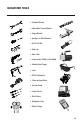
SUGGESTED TOOLS • Standard Wrench • Adjustable/Crescent Wrench • Torque Wrench • Hex Keys or Allen Wrenches • Drill & Drill Bits • Hole Saw • Pipe Cutter • Screw drivers (Phillips & Flat blade) • Manifold and Gauges • Level • R410A Flaring Tool • Clamp on Amp Meter • Vacuum Pump • Safety Glasses • Work Gloves • Refrigerant Scale • Micron Gauge 6
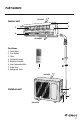
PART NAMES Indoor unit Air inlet 1 2 3 4 Air outlet Part Name 1. 2. 3. 4. 5. 6. 7. 8. Front Panel Aux.
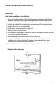
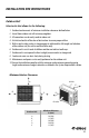
INSTALLATION SITE INSTRUCTIONS Indoor Unit Select a site that allows for the following: 1. Ensure the installation complies with the installation minimum dimensions (defined below) and meets the minimum and maximum connecting piping length and maximum change in elevation as defined in the System Requirements section. 2. Air inlet and outlet will be clear of obstructions, ensuring proper airflow throughout the room. 3. Condensate can be easily and safely drained. 4.
INSTALLATION SITE INSTRUCTIONS Outdoor Unit Select a site that allows for the following: 1. 2. 3. 4. 5. 6. 7. 8. 9. Outdoor location meets all minimum installation clearances defined below. Sound from outdoor unit will not annoy neighbors. All connections can be easily made to indoor unit. Air inlet and outlet will be clear of obstructions to ensure proper airflow.
INDOOR UNIT INSTALLATION A C B INDOOR UNIT DIMENSIONS in (mm) Model A B C SAP09HP230V1AH 38.2 (970) 11.8 (300) 8.9 (225) SAP12HP230V1AH 38.2 (970) 11.8 (300) 8.9 (225) SAP18HP230V1AH 42.5 (1080) 12.8 (325) 9.7 (247.5) SAP4HP230V1AH 42.5 (1080) 12.8 (325) 9.7 (247.5) Installation of Mounting Bracket 1. Attach the mounting bracket to the indoor unit. 2. Find the horizontal center of the indoor unit. 3. Mark the center of the indoor unit on mounting bracket for future reference.
INDOOR UNIT INSTALLATION Mounting Bracket Diagrams and Dimensions 4 27 7 3/16 Φ 2 3/4 Φ 2 3/4 1 1/2 1 1/2 7 1/2 5 1/2 9,000 and 12,000 Units 8 1/8 27 7 5/16 Φ2 3/4 Φ2 3/4 1 5/8 1 5/8 6 18,000 AND 24,000 UNITS 3 1/8 11
OUTDOOR UNIT INSTALLATION Outdoor Unit Dimensions C A A B D D E OUTDOOR UNIT DIMENSIONS in (mm) Model A B C D E SAP09HP230V1AO 21.7 (551) 14.9 (378) 23.5 (597) 35.4 (899) 13.9 (353) SAP12HP230V1AO 21.7 (551) 14.9 (378) 23.5 (597) 35.4 (899) 13.9 (353) SAP18HP230V1AO 24.0 (610) 16.8 (427) 31.1 (790) 38.6 (980) 14.6 (370) SAP24HP230V1AO 24.0 (610) 16.8 (427) 31.1 (790) 38.6 (980) 14.
OUTDOOR UNIT INSTALLATION Ground Pad or Wall Hangers Installation 1. 2. 3. 4. Determine proper location for outdoor unit. Follow all instructions provided by manufacturer for installing wall hangers or ground pad. Verify the wall hangers or ground pad can safely support the weight of the outdoor unit. Verify the wall hangers or ground pad is level and meets all outdoor dimensional clearances.
PIPING INSTALLATION Refrigerant Piping Drill Hole in Wall If indoor unit refrigerant piping is going to exit from the rear: 1. It is recommended that the refrigerant pipe flare connectors extend through the wall to the outside. In some situations field-fabricated piping extensions will be required to extend the indoor unit refrigerant flare connections to the outside of the wall. 2. Use mounting bracket diagrams and dimensions to find and mark the proper location for the wall hole.
PIPING INSTALLATION Refrigerant Piping CAUTION Use refrigeration grade piping ONLY. Uses of other piping will void the Manufacturer’s Warranty. Piping Preparation: 1. Do not open service valves or remove protective caps on pipes until all connections are made. 2. Keep tubing free of dirt, sand, moisture and contaminants. 3. Insulate each refrigerant pipe and condensate hose with minimum 3/8” (10 mm) wall thermal pipe insulation. 4.
PIPING INSTALLATION Refrigerant Piping Piping Connections to Indoor Unit (con’t): 4. Properly align piping and tighten flare nut using a standard wrench and a torque wrench as shown in figure to the below. Carefully tighten flare nuts to correct torque level referring to the Torque Table at bottom of page. NOTE: Over tightening may damage flare connections and cause leaks. 5. Individually insulate refrigerant pipes to prevent sweating. Insulate pipes Piping Connections to Outdoor Unit: 1.
PIPING INSTALLATION Indoor Drain Piping The Sapphire indoor wall unit uses a gravity drain system. There is no internal condensate pump. The drain hose must slope downward with no kinks, raises or fluctuations. NOTE: The drain tube cannot be field re-located from the Left to the Right side of the indoor unit. 1. Connect the field supplied drain hose to the outlet pipe of indoor wall unit. A field supplied transition or adapter may be required. Outlet pipe Drain hose Drain hose 2.
POWER AND WIRING INSTALLATION System Wiring Diagrams 9,000 and 12,000 ButH Indoor Unit Outdoor Unit Blue N1 Black 2 Brown 3 Grn/Yel GND N(1) L1 2 2 3 L2 GND GND Interconnecting Wires Black L1 White L2 Grn/Yel GND Main Power Wires 18,000 & 24,000 ButH Indoor Unit N(1) 2 3 GND Outdoor Unit Blue N(1) Black 2 Brown Grn/Yel Interconnecting Wires 3 L1 L2 GND Black L1 White L2 Grn/Yel GND Main Power Wires 18
POWER AND WIRING INSTALLATION Indoor Unit Wire Connections WARNING Disconnect all electrical power to indoor and outdoor units including disconnects, fuses and circuit breakers. Lockout and tag all disconnect switches. 1. Open front cover of indoor unit and remove field wiring terminal block cover. 2. Pull interconnecting wires up from back of indoor unit and position in close to the terminal block on indoor unit.
POWER AND WIRING INSTALLATION Outdoor Unit Wire Connections WARNING Disconnect all electrical power to unit including disconnects, fuses and circuit breakers. Lockout and tag all disconnect switches. 1. Remove the service panel on right side of the outdoor unit. 2. Insert interconnecting wires and main power wires through the wire holes on conduit mounting bracket. Cable Cross Board 3. Secure main power conduit (and interconnecting wire conduit, if required) with locking nuts to conduit mounting bracket.
TESTING AND INSPECTION Leaking Test 1. Connect the charging hose of the manifold valve to charge the end of the low-pressure valve. 2. Add dry nitrogen to a pressure of 200 lbs. Tightly close both high- and low-pressure valves. 3. Leak-test flare fittings with soap bubbles. If no leak is detected, release nitrogen. CAUTION Use vacuum pump, rather than refrigerant, to discharge air when installing the unit.
TESTING AND INSPECTION Vacuum Procedure (con’t) 7. Confirm that manifold valves are closed and disconnect the vacuum pump. 8. Open the service valves to the fully ‘back-seat’ position to let the refrigerant flow to the indoor unit and balance the pressure in system. Important: Do not allow air to enter the connection pipe when removing the hose. 9. Replace service valve caps and tighten.
TESTING AND INSPECTION □ Turn on main power to indoor and outdoor units. Start-up Checklist □ Press the ON button on the remote controller. • Verify the system is not displaying an error code on the indoor unit display. □ Press the Mode button to Cooling. • Verify the remote controller display turns ON and the indoor unit display is ON. Adjust the room setpoint to bring the system on in cooling mode. The system should start cooling mode within 3-5 minutes.
TROUBLESHOOTING PROBLEM CAUSE/SOLUTION System does not restart. Cause: The system has a built-in three-minute delay to prevent short and/or rapid cycling of the compressor. Solution: Wait three minutes for the protection delay to expire. Indoor unit emits unpleasant odor when started Cause: Typically unpleasant odors are the result of mold or mildew forming on the coil surfaces or the air filter. Solution: Wash indoor air filter in warm water with mild cleaner.
TROUBLESHOOTING PROBLEM CAUSE/SOLUTION Water leaking from the indoor unit into the room. Cause: While it is normal for the system to generate condensate water in cooling mode, it is designed to drain this water via a condensate drain system to a safe location. Solution: If water is leaking into the room, it may indicate one of the following. • The indoor unit is not level right to left. Level indoor unit. • The condensate drain pipe is restricted or plugged.
DIAGNOSTIC CODES Troubleshooting The Sapphire System has on board diagnostics. The outdoor unit will provide status indicators. The indoor wall unit and remote controller will display error codes. The following is a summary of the codes with explanation: Malfunction Name Indoor Unit Display Outdoor Unit Indicators Yellow Possible Causes Red 1) Over charged with refrigerant. 2) Blocked or dirty outdoor coil .
DIAGNOSTIC CODES Malfunction Name Indoor Unit Display Outdoor Unit Indicators Yellow Possible Causes Red Indoor Ambient Temperature Sensor Malfunction F1 1) Loose or bad connection between sensor and control board. 2) Indoor ambient temperature sensor damaged. 3) Control board malfunction. Indoor Coil Temperature Sensor Malfunction F2 1) Loose or bad connection between sensor and control board. 2) Indoor coil temperature sensor damaged. 3) Control board malfunction.
DIAGNOSTIC CODES Malfunction Name Indoor Unit Display Outdoor Unit Indicators Yellow Possible Causes Red IPM Module Protection H5 Indoor DC Fan Motor Malfunction H6 1) Loose connections between fan motor and control board. 2) Fan motor or blower wheel bearings malfunction. 3) Control board malfunction. Compressor De-Synchronized Malfunction H7 1) Compressor voltage is not balance. 2) Control board malfunction. 3) Compressor malfunction.
CARE AND CLEANING WARNING Take notice of the following items before cleaning the Sapphire indoor wall unit. • To avoid electric shock or injury, do not attempt to clean the unit unless it has been turned off and disconnected from the main power supply. • Do not wash the unit with water; this may cause an electric shock. • During cleaning, be sure to use a stable standing platform. Air Filter Cleaning Changing your air filter on a regular basis prevents many problems.
GREE ELECTRIC APPLIANCES, INC. www.greecomfort.com PRODUCT & INSTALLATION RECORD For your convenience, please record the model and serial numbers of your new equipment in the spaces provided. This information, along with the installation data and dealer contact information, will be helpful should your system require maintenance or service. UNIT INFORMATION Outdoor Unit: Model No. Serial No. Indoor Unit: Model No. Serial No.