CEILING CASSETTE INSTALLATION MANUAL Models: Indoor Unit UMAT18HP230V1AC UMAT24HP230V1AC UMAT30HP230V1AC UMAT36HP230V1AC UMAT42HP230V1AC UMAT48HP230V1AC Outdoor Unit UMAT18HP230V1AO UMAT24HP230V1AO UMAT30HP230V1AO UMAT36HP230V1AO UMAT42HP230V1AO UMAT48HP230V1AO
Thank you for choosing a Ceiling Cassette Ductless Heat Pump System for your customer. Please read this installation manual carefully before installing and starting up the Ceiling Cassette Ductless System. Take a moment to fill out the product and installation form on the back cover. Retain both the manual and installation record for future reference. Table of Contents Safety Precautions . . . . . . . . . . . . . . . . . . . . . . . . . . . . . . . . . . . . . . . . . . . . 2 Nomenclature . . . . . . . .
SAFETY PRECAUTIONS Please read the following before installation. This is the safety alert symbol. It is used to alert you to potential personal injury hazards. Obey all safety messages that follow this symbol to avoid possible injury or death. WARNING This mark indicates procedures which, if improperly performed, might lead to the death or serious injury of the user.
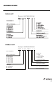
NOMENCLATURE Indoor unit Example: UMAT18HP230V1AC Outdoor unit Example: UMAT18HP230V1AO UMAT 18 HP 230V 1 A O Series Designation UMAT – U-Match Series Cooling Capacity 18 - 18,000 BtuH 24 - 24,000 BtuH 30 - 30,000 BtuH 36 - 36,000 BtuH 42 - 42,000 BtuH 48 - 48,000 BtuH Product Type S - System O - Outdoor Units H - Indoor High Wall D - Indoor Duct C - Indoor Cassette F - Indoor Floor/Ceiling Revision Level Style/Color Designation Model Type AC - Cooling Only HP - Heat Pump HC - Heat/Cool Electrical
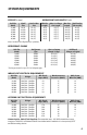
SYSTEM REQUIREMENTS REFRIGERANT LINE LENGTHS ft (m) PIPE SIZE in (mm) Unit Size (BtuH) Liquid Line 18,000 24,000 30,000 36,000 42,000 48,000 1/4 (6) 3/8 (10) 3/8 (10) 3/8 (10) 3/8 (10) 3/8 (10) Suction/Gas Line Min Line Length 1/2 (12) 5/8 (15) 5/8 (15) 5/8 (15) 5/8 (15) 5/8 (15) 10 (3) 10 (3) 10 (3) 10 (3) 10 (3) 10 (3) Max. Pre-Charge Max Line Max Elevation Line Length Length (ID over OD) 25(7.5) 25(7.5) 25(7.5) 25(7.5) 25(7.5) 25(7.
SUGGESTED TOOLS • Standard Wrench • Adjustable/Crescent Wrench • Torque Wrench • Hex Keys or Allen Wrenches • Drill & Drill Bits • Hole Saw • Pipe Cutter • Screw drivers (Phillips & Flat blade) • Manifold and Gauges • Level • R410A Flaring Tool • Clamp on Amp Meter • Vacuum Pump • Safety Glasses • Work Gloves • Refrigerant Scale • Micron Gauge 5
System Schematic 1 Indoor unit 2 3 4 Air outlet 5 Air inlet System Components* 1. 2. 3. 4. Indoor Power Supply Drain Pipe Communication Cable Decorative Discharge Air Grille (sold separately) 5. Refrigeration Pipes 6. XK60 Tether Controller (sold separately) 7. Remote Controller 8. Service Cover 9. Communication Cable 10. Front Panel 11. Outdoor Power Supply 12. Liquid Pipe 13. Gas Pipe 14.
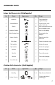
STANDARD PARTS Indoor Unit Accessories (Field Supplied) No.
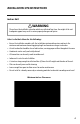
INSTALLATION SITE INSTRUCTIONS Indoor Unit WARNING The unit must be installed in a location which can withstand four times the weight of the unit. Inadequate support may result in serious property damage and injuries. Select a site that allows for the following: • Ensure the installation complies with the installation minimum dimensions and meets the minimum and maximum connecting piping length and maximum change in elevation.
INSTALLATION SITE INSTRUCTIONS Outdoor Unit Select a site that allows the following: WARNING The unit should be installed level on a pad that can support twice the weight of the unit. If the outdoor unit will be exposed to strong winds, it must be adequately secured. CAUTION Do not install the unit at a location where the distance exceeds the maximum pipe length indicated in the table. The maximum length of the connection pipe is listed in the System Requirements section. 1.
INDOOR UNIT DIMENSIONS 18K Indoor Unit Dimensions INDOOR UNIT DIMENSIONS in (mm) Model UMAT18HP230V1AC A B C D E F G H I J 26-3/8 (670) 23-1/2 (597) 23-1/4 (591) 22-5/8 (575) 5-3/4 (146) 9-1/2 (241) 26-1/8 (664) 9-1/4 (235) 22-5/8 (575) 19-7/8 (505) 24K-42K Indoor Unit Dimensions INDOOR UNIT DIMENSIONS in (mm) Model A B C D E F G H I UMAT24HP230V1AC 37-3/8 (949) 32-3/4 (832) 30-3/4 (781) 26-3/4 (679) 6-1/4 (159) 9-1/2 (241) 36-1/8 (918) 8-1/2 (216) 39-1/8 (994) UM
INDOOR UNIT DIMENSIONS 48K Indoor Unit Dimensions INDOOR UNIT DIMENSIONS in (mm) Model UMAT48HP230V1AC A B C D E F 41 (1041) 35-7/8 (911) 33-1/8 (841) 31 (787) 6-3/4 (171) 11-3/8 (289) Laying Out Indoor Location • Locate the factory supplied installation template included in carton. • Use the template to make an opening in the ceiling for the ceiling cassette main body. • Mark the position of the 4 hanger bolts, refrigerant lines and condensate drain pipes.
INDOOR UNIT INSTALLATION Indoor Unit Hanger Mounting Depending on the type of ceiling, attach the threaded hanger bolts securely to the support stud. Before lifting the indoor unit to the installation location, insert the upper nuts, flat washers (with insulation), flat washers (without insulation), lower nuts and double locking nuts on the threaded hanger bolts. Nut Threaded Hanger Bolt Washer Washer Nut Nut NOTE: The hanger bolts, nuts, and washers are field supplied.
OUTDOOR UNIT INSTALLATION WARNING The unit should be located with the unit support feet firmly on the equipment pad. If the outdoor unit is exposed to wind, it must be properly secured.
OUTDOOR UNIT INSTALLATION Condensate Drainage of the Outdoor Unit The outdoor unit should be installed with a drain pipe to drain condensate water during the heating mode. 1. Insert the drain joint (included) into the selected hole located on the bottom of the base pan and then connect the drain hose (field supplied) to the drain joint. 2. All other holes must be sealed with plugs (included) to avoid water leaks, except for the drain pipe mounting hole. 3.
PIPING INSTALLATION Refrigerant Piping Drill Hole in Wall Indoor 1. Locate and mark proper location for the wall hole. Outdoor Wall Hole Sleeve 2. Cut the 2 3/4” wall hole with a 5° to 10° downward slant to the outdoors. Seal Hole 3. Insert a wall sleeve (field supplied) into hole to to prevent damage to refrigerant pipes, insulation, condensate drain hose and wiring. Hole Size Wall Hole Diagram 4.
PIPING INSTALLATION Indoor Unit Pipe Connections 1. Feed refrigerant pipes, drain hose and communication cable assembly through wall hole from outdoor to the Ceiling Cassette. 2. Pull the piping assembly to the indoor unit. Carefully bend refrigerant pipes to meet indoor unit connection ports. Use proper tools to avoid kinks. Oil applied Copper 3. Add a small amount of refrigerant oil to (to reduce friction piping with the flare nut) both ends of the flare fittings. 4.
PIPING INSTALLATION Outdoor Unit Pipe Connections 1. Remove service valve cover (if provided) to access the service valves and refrigerant ports. Service Valve Cover 2. Carefully bend and adjust length of refrigerant pipes to meet outdoor unit service valve connections with proper tools to avoid kinks. Gas pipe Liquid pipe Pipe coupling 3. Add a small amount of refrigerant oil to both ends of the flare fittings. or 3-way valve 4.
PIPING INSTALLATION C Indoor Condensate Drain Piping WARNING Observe all local sanitary codes when installing condensate drains. It is recommended to install the condensate drain system with hard polyvinyl chloride (PVC) pipe and matching connectors. Use piping of the same diameter as the unit connection, or of the same diameter of the raising section. The Ceiling Cassette drainage port diameter is 1-in (25 mm) OD. Pitch the condensate drain pipe at a gradual 2.
POWER AND WIRING INSTALLATION WARNING 1. Before obtaining access to terminals, all electrical supply circuits must be disconnected. 2. Always use an independent circuit and provide an independent circuit breaker to supply power to the system. 3. Use a circuit breaker with adequate capacity to meet the requirements of the total system. 4. All circuit breakers or fuses for the indoor and outdoor units should be installed per the National Electric Code (NEC) and local regulations. 5.
POWER AND WIRING INSTALLATION Electric Wiring Between Indoor Unit and Outdoor Unit Typical Wiring Diagram Single-phase units (18K~48K) Indoor Unit Electrical Wiring Locate and remove the electrical box cover to access wire terminals. Indoor Communication Wiring The recommended communication cable size is a minimum 18/2 AWG stranded bare copper conductors THHN 300V unshielded wire. Use shielded cable if installation is in close proximity of RF and EMI transmitting devices.
POWER AND WIRING INSTALLATION Tether Controller Wiring (optional) Use a minimum 18-2 AWG wire (field supplied) to connect Tether Controller to the indoor unit. Route wire from Tether Controller into electrical box. Locate wire terminals H1 and H2. Connect Tether Controller wires to H1 and H2. Verify wires are secure, not loose and no external force on wires affects the connections at the terminals. Replace and Secure indoor unit electric box cover.
CONTROLLER INSTALLATION AND SETUP (Optional) The following is a brief overview of the Wired Tether Controller installation. See Owner's Manual for more detailed instructions for setup and operation. Preparation for Installation Select a proper location on the wall for mounting the Tether Controller. Install switch box, if required by code. The maximum wire length between indoor and Tether Controller is 30-ft. Run communication cable (as desired) between indoor unit and selected wall mounting location.
CONTROLLER INSTALLATION AND SETUP (Optional) Setting Double Indoor Room Sensors This series of Ceiling Cassette has two indoor room sensors, if an optional wired Tether Controller is installed. One is located at the air intake of the Ceiling Cassette and the other is located inside the Tether Controller. The user can select one from the two indoor room sensors on the basis of their own preference. Refer to the I-FEEL Function in the Tether Controller Owner's Manual for detailed instructions.
FRESH AIR INTAKE Connecting Fresh Air Duct The indoor ceiling cassettes have a fresh air intake port for ventilation. A booster fan and duct (field supplied) must be used to feed outdoor air to the indoor unit. Determine the duct diameter, length and booster fan size based on the required airflow. See table below for duct and hole sizes: Unit Size (BtuH) Hole Diameter inch (mm) Min. Duct Diameter 18,000 24,000-48,000 2.375 (60) 2.875 (73) 2.5 (64) 3.
DECORATIVE GRILLE INSTALLATION Mounting Decorative Grille Ceiling Cassette main body 1. Carefully unpack decorative grille and align the decorative grille to the Ceiling Cassette main body. 2. Temporarily attach the decorative grille to the ceiling cassette main body at two (2) corner points. Refrigerant pipes Hook & latch Hook & latch Hook & latch 3. Locate the two (2) Swing Louver electrical connectors on the decorative grille. Height adjustment screw 4.
TESTING AND INSPECTION Pipe Testing Gauge manifold Pressure gauge (low-pressure) Pressure gauge (hi-pressure) Switch (low-pressure) Switch (hi-pressure) Connection pipe (to indoor unit) Connection pipe Cap Liquid valve Gas valve Service pipe Hose Service port Cap Cap Hose Hose with the valve pin Vacuum pump Leak Test Refrigerant lines should be pressurized prior to evacuating system to check for leaks. Use only dry nitrogen with a pressure regulator for pressurizing unit.
TESTING AND INSPECTION Vacuum Procedure Important: Use a quality Micron Gauge to measure and validate the proper system vacuum level achieved. Do not rely on the scale of a“bourbon tube”type gauge set to validate the depth and quality of the vacuum. 1. Remove the caps of the liquid valve, gas valve and service port. 2. Connect gauge manifold and micron gauge to the service ports provided at the liquid and suction service valves. 3. Connect a vacuum pump to the manifold gauge. 4.
TESTING AND INSPECTION Start-up Checklist □ Turn on main power to indoor and outdoor units. • Verify the system is not displaying an error code on the indoor unit display. □ Point the Remote Controller at the Floor/Ceiling unit and Press the On button. • Verify the remote controller display turns ON and the Power Indicator lights up on the Floor/Ceiling unit. □ Press the Mode button to Cooling. Adjust the room setpoint to bring the system on in cooling mode.
TROUBLESHOOTING PROBLEM CAUSE/SOLUTION System does not restart. Cause: The system has a built-in three-minute delay to prevent short and/or rapid cycling of the compressor. Solution: Wait three minutes for the protection delay to expire. Indoor unit emits unpleasant odor when started Cause: Typically unpleasant odors are the result of mold or mildew forming on the coil surfaces or the air filter. Solution: Wash indoor air filter in warm water with mild cleaner.
TROUBLESHOOTING PROBLEM CAUSE/SOLUTION Water leakage from the outdoor unit. Cause: It is normal for the outdoor unit to generate condensate water in the reverse cycle heating and defrost mode. Solution: This is normal. No action is required. Water leaking from the indoor unit into the room. Cause: While it is normal for the system to generate condensate water in cooling mode, it is designed to drain this water via a condensate drain system to a safe location.
DIAGNOSTIC CODES The U-Match System has on board diagnostics. The indoor unit and Tether Controller will display error codes. The following is a summary of the codes with explanation: Error Codes No. 1 2 3 4 5 6 Error Code E1 E2 E3 Origin of Malfunction Description High Pressure Protection High Pressure Switch If outdoor unit detects the high pressure switch is cut off for 3-sec successively, high pressure protection will occur.
DIAGNOSTIC CODES Error Codes No. Error Code Malfunction Name Origin of Malfunction 7 E9 Condensate Overflow Protection Overflow Switch If indoor unit detects the condensate overflow switch warning for 8-sec successively, the system will enter condensate overflow protection. The unit will shut off and will not recover automatically. Switch unit off and then switch it on to eliminate this malfunction.
DIAGNOSTIC CODES Error Codes No. Error Code Malfunction Name Origin of Malfunction Description 14 ee Outdoor Drive Memory Chip Malfunction Outdoor Drive Board If the memory chip of outdoor drive circuit board fails, the unit will not start. The unit will not recover automatically. If thermo junction cannot be eliminated after switching off the unit and then energizing the unit several times, replace the outdoor drive circuit board.
GREE ELECTRIC APPLIANCES, INC. www.greecomfort.com PRODUCT & INSTALLATION RECORD For your convenience, please record the model and serial numbers of your new equipment in the spaces provided. This information, along with the installation data and dealer contact information, will be helpful should your system require maintenance or service. UNIT INFORMATION Outdoor Unit: Model No. Serial No. Indoor Unit: Model No. Serial No.