
Service Manual
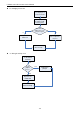
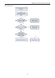
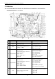
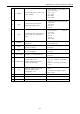
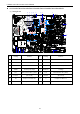
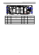
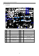
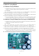
Table Of Contents
- 目录
- 第一部分 产品篇
- 第二部分 控制篇
- CONTROL
- 1 OPERATION FLOWCHART
- 2 WIRELESS REMOTE CONTROLLER
- 3 WIRED CONTROLLER
- 4 OPERATION INSTRUCTION OF SPECIAL FUNCTIONS
- 4.1 Setting of Filter Clean Reminder Function
- 4.2 Low Temperature Drying Function
- 4.3 Lock Function
- 4.4 Memory Function
- 4.5 Door Control Function/Human Sensitive Function
- 4.6 Switch between Fahrenheit and Centigrade
- 4.7 Enquiry of Ambient Temperature
- 4.8 Enquiry of Historical Malfunction
- 4.9 Debugging Function
- 4.9.1 Setting ambient temperature sensor (dual ambient temperature sensors function)
- 4.9.2 Selecting three speeds in high speed and three speeds in low speed of indoor fan motor
- 4.9.3 Displaying setting of freeze protection error code
- 4.9.4 Setting refrigerant lacking protection function
- 4.9.5 Selecting blowing residual heating of indoor unit
- 4.9.6 Mode selecting of compressor electric heating belt
- 4.9.7 Selecting low-power consumption mode
- 4.9.8 Selecting door control function
- 4.9.9 Selecting human sensitive function
- 4.9.10 Selecting long-distance monitoring or centralized controller
- 4.9.11 Selecting fan mode of indoor fan motor
- 4.9.12 Selecting compensation of temperature sensor at air return
- 5 INSTALLATION OF WIRED CONTROLLER
- 6 TROUBLESHOOTING
- 7 CENTRALIZED CONTROLLER
- 7.1 Smart Zone Controller
- 7.2 Additional Special Functions
- 7.2.1 Door control function
- 7.2.2 Human sensitive function
- 7.2.3 MODBUS interface
- 7.2.4 Connect to interface of centralized controller:
- 7.2.5 Light board control:
- 7.2.6 Malfunction output of relay:
- 7.2.7 Reserved fresh air valve interface for duct type unit
- 7.2.8 Interface of anion generator
- 7.2.9 Chassis electric heating belt of outdoor unit is optional
- CONTROL
- 第三部分 安装篇
- INSTALLATION
- 1 INDOOR UNIT INSTALLATION
- 1.1 Installation of Duct Type
- 1.2 Installation of Floor Ceiling Type
- 1.3 Installation of Cassette Type
- 1.3.1 Before Installation
- 1.3.2 Installation Site
- 1.3.3 Installing the Main Body Unit
- 1.3.4 Installing the Suspension Bolts
- 1.3.5 Leveling
- 1.3.6 The Panel Installation
- 1.3.7 Dimension Data
- 1.3.8 Installation of Drain Piping
- 1.3.9 Installing the Drain Pipes
- 1.3.10 Precautions When Doing Riser Piping Work
- 1.3.11 Testing of Drain Piping
- 2 OUTDOOR UNIT INSTALLATION
- 3 REFRIGERATION PIPING WORK
- 3.1 Refrigeration Piping Work Procedures and Caution in Connecting
- 3.2 Specification of Connection Pipe
- 4 ELECTRIC WIRING WORK
- 1 INDOOR UNIT INSTALLATION
- INSTALLATION
- 第四部分 维护篇(上)4.1~4.3
- 第四部分 维护篇(中)4.4拆装
- 第四部分 维护篇(下)4.5爆炸图及清单

U-Match Series DC Inverter Service Manual
111
2.3 Interface
GUHD18ND3FO/GUHD24ND3FO/ GUHD30ND3FO/ GUHD36ND3FO / GUHD42ND3FO
/GUHD48ND3FO Main Control Board
NO.
SILK-SCREEN
INTERFACE
INTERFACE INSTRUCTION
1
AC-L
Live wire input
Live wire input
2
AC-N
Neutral wire input
Neutral wire input
3
PWR 1
Control power output[1- DC bus
voltage, 3- GND]
Power supply interface to the drive
1-pin: DC bus voltage
3-pin: DC bus GND
4
DC_MOTOR2
DC fan motor2
1-pin: Power supply of fan motor
3-pin: Fan GND
4-pin: +15V
5-pin: Signal control
6-pin: NC
Interface of DC fan motor
1-pin: DC bus voltage
2-pin: Suspended
3-pin: DC bus GND
4-pin: +15V
5-pin: Control signal input
6-pin: Not connected
5
DC_MOTOR1
DC fan motor1
1-pin: Power supply of fan motor
3-pin: Fan GND
4-pin: +15V
5-pin: Signal control
6-pin: Signal Feedback
Interface of DC fan motor
1-pin: DC bus voltage
2-pin: Suspended
3-pin: DC bus GND
4-pin: +15V
5-pin: Control signal input
6-pin: DC fan motor feedback
6
CN3
Control power output[1-GND
、
2-18V
、
3-15V]
Power supply interface to the drive
1-pin: GND
2-pin: +18V
3-pin: +15V