
Service Manual
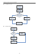
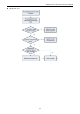
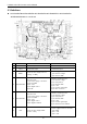
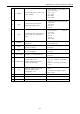
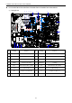
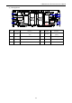
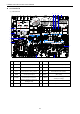
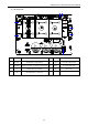
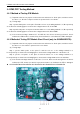
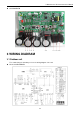
Table Of Contents
- 目录
- 第一部分 产品篇
- 第二部分 控制篇
- CONTROL
- 1 OPERATION FLOWCHART
- 2 WIRELESS REMOTE CONTROLLER
- 3 WIRED CONTROLLER
- 4 OPERATION INSTRUCTION OF SPECIAL FUNCTIONS
- 4.1 Setting of Filter Clean Reminder Function
- 4.2 Low Temperature Drying Function
- 4.3 Lock Function
- 4.4 Memory Function
- 4.5 Door Control Function/Human Sensitive Function
- 4.6 Switch between Fahrenheit and Centigrade
- 4.7 Enquiry of Ambient Temperature
- 4.8 Enquiry of Historical Malfunction
- 4.9 Debugging Function
- 4.9.1 Setting ambient temperature sensor (dual ambient temperature sensors function)
- 4.9.2 Selecting three speeds in high speed and three speeds in low speed of indoor fan motor
- 4.9.3 Displaying setting of freeze protection error code
- 4.9.4 Setting refrigerant lacking protection function
- 4.9.5 Selecting blowing residual heating of indoor unit
- 4.9.6 Mode selecting of compressor electric heating belt
- 4.9.7 Selecting low-power consumption mode
- 4.9.8 Selecting door control function
- 4.9.9 Selecting human sensitive function
- 4.9.10 Selecting long-distance monitoring or centralized controller
- 4.9.11 Selecting fan mode of indoor fan motor
- 4.9.12 Selecting compensation of temperature sensor at air return
- 5 INSTALLATION OF WIRED CONTROLLER
- 6 TROUBLESHOOTING
- 7 CENTRALIZED CONTROLLER
- 7.1 Smart Zone Controller
- 7.2 Additional Special Functions
- 7.2.1 Door control function
- 7.2.2 Human sensitive function
- 7.2.3 MODBUS interface
- 7.2.4 Connect to interface of centralized controller:
- 7.2.5 Light board control:
- 7.2.6 Malfunction output of relay:
- 7.2.7 Reserved fresh air valve interface for duct type unit
- 7.2.8 Interface of anion generator
- 7.2.9 Chassis electric heating belt of outdoor unit is optional
- CONTROL
- 第三部分 安装篇
- INSTALLATION
- 1 INDOOR UNIT INSTALLATION
- 1.1 Installation of Duct Type
- 1.2 Installation of Floor Ceiling Type
- 1.3 Installation of Cassette Type
- 1.3.1 Before Installation
- 1.3.2 Installation Site
- 1.3.3 Installing the Main Body Unit
- 1.3.4 Installing the Suspension Bolts
- 1.3.5 Leveling
- 1.3.6 The Panel Installation
- 1.3.7 Dimension Data
- 1.3.8 Installation of Drain Piping
- 1.3.9 Installing the Drain Pipes
- 1.3.10 Precautions When Doing Riser Piping Work
- 1.3.11 Testing of Drain Piping
- 2 OUTDOOR UNIT INSTALLATION
- 3 REFRIGERATION PIPING WORK
- 3.1 Refrigeration Piping Work Procedures and Caution in Connecting
- 3.2 Specification of Connection Pipe
- 4 ELECTRIC WIRING WORK
- 1 INDOOR UNIT INSTALLATION
- INSTALLATION
- 第四部分 维护篇(上)4.1~4.3
- 第四部分 维护篇(中)4.4拆装
- 第四部分 维护篇(下)4.5爆炸图及清单

U-Match Series DC Inverter Service Manual
117
2.4 IPM, PFC Testing Method
2.4.1 Method of Testing IPM Module
(1) Preparation before test: prepare a universal meter and turn to its diode option, and then remove
the wires U, V, W of the compressor after it is powered off for one minute.
(2) Testing Steps
Step 1: put the black probe on the place P and the red one on the wiring terminal U, V, W respectively
as shown in the following figure to measure the voltage between UP, VP and WP.
Step 2: put the red probe on the place N and the black one on the wiring terminal U, V, W respectively
as shown in the following figure to measure the voltage between NU, NV and NW.
(3) If the measured voltages between UP, VP, WP, NU, NV, NV are all among 0.3V-0.7V, then it
indicates the IPM module is normal; If any measured valve is 0, it indicates the IPM is damaged.
2.4.2
Method of Testing PFC Module Short Circuit (only for GUHD48ND3FO):
(1) Preparation before test: prepare a universal meter and turn to its diode option, and then remove
the wires L1-2, L2-1 after it is powered off for one minute.
(2) Testing Steps
Step 1: put the black probe on the place P and the red one on the wiring terminal L1-2,
L2-1respectively as shown in the following figure to measure the voltage between L1-2P and.L2-1 P.
Step 2: put the red probe on the place N and the black one on the wiring terminal L1-2,
L2-1respectively as shown in the following figure to measure the voltage between N L1-2 and NL2-1.
(3) If the measured voltages between L1-2P ,L2-1 P, N L1-2 , NL2-1 are all among 0.3V-0.7V, then it
indicates the PFC module is normal; If any measured valve is 0, it indicates the PFC is damaged.
GUHD18ND3FO/GUHD24ND3FO/ GUHD30ND3FO /GUHD36ND3FO/ GUHD42ND3FO