
Service Manual
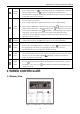
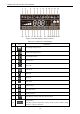
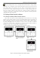
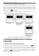
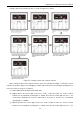

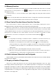
Table Of Contents
- 目录
- 第一部分 产品篇
- 第二部分 控制篇
- CONTROL
- 1 OPERATION FLOWCHART
- 2 WIRELESS REMOTE CONTROLLER
- 3 WIRED CONTROLLER
- 4 OPERATION INSTRUCTION OF SPECIAL FUNCTIONS
- 4.1 Setting of Filter Clean Reminder Function
- 4.2 Low Temperature Drying Function
- 4.3 Lock Function
- 4.4 Memory Function
- 4.5 Door Control Function/Human Sensitive Function
- 4.6 Switch between Fahrenheit and Centigrade
- 4.7 Enquiry of Ambient Temperature
- 4.8 Enquiry of Historical Malfunction
- 4.9 Debugging Function
- 4.9.1 Setting ambient temperature sensor (dual ambient temperature sensors function)
- 4.9.2 Selecting three speeds in high speed and three speeds in low speed of indoor fan motor
- 4.9.3 Displaying setting of freeze protection error code
- 4.9.4 Setting refrigerant lacking protection function
- 4.9.5 Selecting blowing residual heating of indoor unit
- 4.9.6 Mode selecting of compressor electric heating belt
- 4.9.7 Selecting low-power consumption mode
- 4.9.8 Selecting door control function
- 4.9.9 Selecting human sensitive function
- 4.9.10 Selecting long-distance monitoring or centralized controller
- 4.9.11 Selecting fan mode of indoor fan motor
- 4.9.12 Selecting compensation of temperature sensor at air return
- 5 INSTALLATION OF WIRED CONTROLLER
- 6 TROUBLESHOOTING
- 7 CENTRALIZED CONTROLLER
- 7.1 Smart Zone Controller
- 7.2 Additional Special Functions
- 7.2.1 Door control function
- 7.2.2 Human sensitive function
- 7.2.3 MODBUS interface
- 7.2.4 Connect to interface of centralized controller:
- 7.2.5 Light board control:
- 7.2.6 Malfunction output of relay:
- 7.2.7 Reserved fresh air valve interface for duct type unit
- 7.2.8 Interface of anion generator
- 7.2.9 Chassis electric heating belt of outdoor unit is optional
- CONTROL
- 第三部分 安装篇
- INSTALLATION
- 1 INDOOR UNIT INSTALLATION
- 1.1 Installation of Duct Type
- 1.2 Installation of Floor Ceiling Type
- 1.3 Installation of Cassette Type
- 1.3.1 Before Installation
- 1.3.2 Installation Site
- 1.3.3 Installing the Main Body Unit
- 1.3.4 Installing the Suspension Bolts
- 1.3.5 Leveling
- 1.3.6 The Panel Installation
- 1.3.7 Dimension Data
- 1.3.8 Installation of Drain Piping
- 1.3.9 Installing the Drain Pipes
- 1.3.10 Precautions When Doing Riser Piping Work
- 1.3.11 Testing of Drain Piping
- 2 OUTDOOR UNIT INSTALLATION
- 3 REFRIGERATION PIPING WORK
- 3.1 Refrigeration Piping Work Procedures and Caution in Connecting
- 3.2 Specification of Connection Pipe
- 4 ELECTRIC WIRING WORK
- 1 INDOOR UNIT INSTALLATION
- INSTALLATION
- 第四部分 维护篇(上)4.1~4.3
- 第四部分 维护篇(中)4.4拆装
- 第四部分 维护篇(下)4.5爆炸图及清单

U-Match Series DC Inverter Service Manual
21
3.2.2 Instruction to Function of Buttons
Table 2-3-2 Instruction to buttons of wired controller
No.
Description
Functions
1
Enter/Cancel
①. Function selection and canceling;
②. Press it for 5s to view the ambient temperature; press Mode button
to select viewing outdoor ambient temperature or indoor ambient
temperature.
2
▲
①. Running temperature setting range of indoor unit:
16~30℃(61~86℉);
②. Timer setting range: 0.5~24hr;
③. Setting of air function level;
④. Setting of energy-saving temperature;
⑤. Setting of cleaning class.
6
▼
3
Fan
Setting of high/medium high/medium/medium low/low/auto fan speed.
4
Mode
Setting of auto/cooling/heating/fan/dry mode of indoor unit.
5
Function
Switch over among these functions of swing/air/sleep/health/
I-Demand/out/turbo/save/e-heater/X-fan/clean/quiet.
7
Timer
Timer setting.
8
On/Off
Turn on/off indoor unit.
4 Mode
and
2 ▲
Memory function
Press Mode and ▲ buttons at the same time for 5s under off state of the
unit to enter/cancel memory function (If memory function is set, indoor
unit will resume original setting state after power failure and then power
recovery. If not, indoor unit is defaulted to be off after power recovery.
Ex-factory setting of memory function is on).
2 ▲
and
6 ▼
Lock
Upon startup of the unit without malfunction or under off state of the unit,
press ▲ and ▼ buttons at the same time for 5s to enter lock state. In this
case, any other buttons won‟t respond when pressing. Repress ▲ and ▼
buttons for 5s to quit lock state.
4 Mode
and
5 Function
Enquiry and
setting of address
of wired
controller
Under off state of the unit, press Mode and Function buttons at the same
time for 5s to set the address. (More details please refer to project
debugging)
5 Function
and
7 Timer
Setting of project
parameters
(More details
please refer to
the Notes)
Under off state of the unit, press Function and Timer buttons at the same
time for 5s to go to the debugging menu. Press Mode button to adjust the
setting items and press ▲ or ▼ buttons to set the actual value.
4 Mode
and
6 ▼
Switch between
Fahrenheit and
Centigrade
Under off state of the unit, press Mode and ▼ buttons at the same time
for 5s to switch between Fahrenheit and Centigrade.
5 Function
and
6 ▼
Viewing historical
malfunction
Continuously press Function and ▼ buttons for 5s to view historical
malfunction. Then press ▲ and ▼ buttons to adjust displayed contents.
The timer displaying position displays the sequence of malfunction and
the detailed error code. The 5th displayed malfunction is the last
malfunction.
1 Enter/Cancel
and
4 Mode
Setting of master
and slave wired
controller
Under off state of the unit, press Enter/Cancel and Mode buttons at the
same time for 5s to set master and slave wired controller. Press ▲ or ▼
button to adjust. (More details please refer to project debugging)