
Service Manual
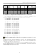
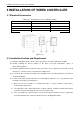
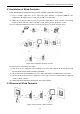
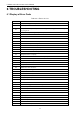
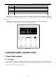
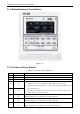
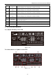
Table Of Contents
- 目录
- 第一部分 产品篇
- 第二部分 控制篇
- CONTROL
- 1 OPERATION FLOWCHART
- 2 WIRELESS REMOTE CONTROLLER
- 3 WIRED CONTROLLER
- 4 OPERATION INSTRUCTION OF SPECIAL FUNCTIONS
- 4.1 Setting of Filter Clean Reminder Function
- 4.2 Low Temperature Drying Function
- 4.3 Lock Function
- 4.4 Memory Function
- 4.5 Door Control Function/Human Sensitive Function
- 4.6 Switch between Fahrenheit and Centigrade
- 4.7 Enquiry of Ambient Temperature
- 4.8 Enquiry of Historical Malfunction
- 4.9 Debugging Function
- 4.9.1 Setting ambient temperature sensor (dual ambient temperature sensors function)
- 4.9.2 Selecting three speeds in high speed and three speeds in low speed of indoor fan motor
- 4.9.3 Displaying setting of freeze protection error code
- 4.9.4 Setting refrigerant lacking protection function
- 4.9.5 Selecting blowing residual heating of indoor unit
- 4.9.6 Mode selecting of compressor electric heating belt
- 4.9.7 Selecting low-power consumption mode
- 4.9.8 Selecting door control function
- 4.9.9 Selecting human sensitive function
- 4.9.10 Selecting long-distance monitoring or centralized controller
- 4.9.11 Selecting fan mode of indoor fan motor
- 4.9.12 Selecting compensation of temperature sensor at air return
- 5 INSTALLATION OF WIRED CONTROLLER
- 6 TROUBLESHOOTING
- 7 CENTRALIZED CONTROLLER
- 7.1 Smart Zone Controller
- 7.2 Additional Special Functions
- 7.2.1 Door control function
- 7.2.2 Human sensitive function
- 7.2.3 MODBUS interface
- 7.2.4 Connect to interface of centralized controller:
- 7.2.5 Light board control:
- 7.2.6 Malfunction output of relay:
- 7.2.7 Reserved fresh air valve interface for duct type unit
- 7.2.8 Interface of anion generator
- 7.2.9 Chassis electric heating belt of outdoor unit is optional
- CONTROL
- 第三部分 安装篇
- INSTALLATION
- 1 INDOOR UNIT INSTALLATION
- 1.1 Installation of Duct Type
- 1.2 Installation of Floor Ceiling Type
- 1.3 Installation of Cassette Type
- 1.3.1 Before Installation
- 1.3.2 Installation Site
- 1.3.3 Installing the Main Body Unit
- 1.3.4 Installing the Suspension Bolts
- 1.3.5 Leveling
- 1.3.6 The Panel Installation
- 1.3.7 Dimension Data
- 1.3.8 Installation of Drain Piping
- 1.3.9 Installing the Drain Pipes
- 1.3.10 Precautions When Doing Riser Piping Work
- 1.3.11 Testing of Drain Piping
- 2 OUTDOOR UNIT INSTALLATION
- 3 REFRIGERATION PIPING WORK
- 3.1 Refrigeration Piping Work Procedures and Caution in Connecting
- 3.2 Specification of Connection Pipe
- 4 ELECTRIC WIRING WORK
- 1 INDOOR UNIT INSTALLATION
- INSTALLATION
- 第四部分 维护篇(上)4.1~4.3
- 第四部分 维护篇(中)4.4拆装
- 第四部分 维护篇(下)4.5爆炸图及清单

U-Match Series DC Inverter Service Manual
28
4.9.3 Displaying setting of freeze protection error code
Under debugging state, press Mode button to adjust to “02” in temperature displaying zone. Timer
zone displays setting state and press ▲ or ▼ button to adjust. There are 2 selections:
(1) Displayed (LCD displays 01)
(2) Not displayed (LCD displays 02)
It is defaulted to be not displayed for export unit and be displayed for domestic unit.
4.9.4 Setting refrigerant lacking protection function
Under debugging state, press Mode button to adjust to “04” in temperature displaying zone. Timer
zone displays setting state and press ▲ or ▼ button to adjust. There are 2 selections:
(1) With refrigerant lacking protection function (LCD displays 01)
(2) Without refrigerant lacking protection function (LCD displays 02)
4.9.5 Selecting blowing residual heating of indoor unit
Under debugging state, press Mode button to adjust to “05” in temperature displaying zone. Timer
zone displays setting state and press ▲ or ▼ button to adjust. There are 2 selections:
(1) Mode 1 (LCD displays 00)
(2) Mode 2 (LCD displays 01)
Note:
Blowing residual heating of indoor unit
Mode 1: Unit stops when reaching temperature point and indoor fan motor does not stop in cooling
mode; after unit stops when reaching temperature point in heating mode, duct type unit and floor ceiling
unit blow residual heat for 60s and then stop indoor unit, while cassette type unit always operates in low fan
speed and blows residual heat for 60s when there is malfunction.
Mode 2: After unit stops when reaching temperature point, the indoor fan motor stops operation with a
10s delay no matter in cooling mode or in heating mode.
4.9.6 Mode selecting of compressor electric heating belt
Under debugging state, press Mode button to adjust to “06” in temperature displaying zone. Timer
zone displays setting state and press ▲ or ▼ button to adjust. There are 2 selections:
(1) Mode 1 (LCD displays 00)
(2) Mode 2 (LCD displays 01)
Notes:
① Mode 1: Compressor electric heating belt starts when outdoor ambient temperature is below
35
℃
(95
℉
) and stops when outdoor ambient temperature is above 37
℃
(99
℉
). When
outdoor ambient temperature is within 35
℃
(95
℉
)~ 37
℃
(99
℉
), the belt will keep its
previous operation state.
② Mode 2: Compressor electric heating belt starts when outdoor ambient temperature is below
-2 (28
℉
) and stops when outdoor ambient temperature is above 0
℃
(32
℉
). When outdoor
ambient temperature is within -2
℃
(28
℉
)~0
℃
(32
℉
), the belt will keep its previous