
Service Manual
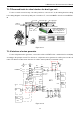

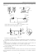
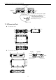
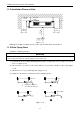
Table Of Contents
- 目录
- 第一部分 产品篇
- 第二部分 控制篇
- CONTROL
- 1 OPERATION FLOWCHART
- 2 WIRELESS REMOTE CONTROLLER
- 3 WIRED CONTROLLER
- 4 OPERATION INSTRUCTION OF SPECIAL FUNCTIONS
- 4.1 Setting of Filter Clean Reminder Function
- 4.2 Low Temperature Drying Function
- 4.3 Lock Function
- 4.4 Memory Function
- 4.5 Door Control Function/Human Sensitive Function
- 4.6 Switch between Fahrenheit and Centigrade
- 4.7 Enquiry of Ambient Temperature
- 4.8 Enquiry of Historical Malfunction
- 4.9 Debugging Function
- 4.9.1 Setting ambient temperature sensor (dual ambient temperature sensors function)
- 4.9.2 Selecting three speeds in high speed and three speeds in low speed of indoor fan motor
- 4.9.3 Displaying setting of freeze protection error code
- 4.9.4 Setting refrigerant lacking protection function
- 4.9.5 Selecting blowing residual heating of indoor unit
- 4.9.6 Mode selecting of compressor electric heating belt
- 4.9.7 Selecting low-power consumption mode
- 4.9.8 Selecting door control function
- 4.9.9 Selecting human sensitive function
- 4.9.10 Selecting long-distance monitoring or centralized controller
- 4.9.11 Selecting fan mode of indoor fan motor
- 4.9.12 Selecting compensation of temperature sensor at air return
- 5 INSTALLATION OF WIRED CONTROLLER
- 6 TROUBLESHOOTING
- 7 CENTRALIZED CONTROLLER
- 7.1 Smart Zone Controller
- 7.2 Additional Special Functions
- 7.2.1 Door control function
- 7.2.2 Human sensitive function
- 7.2.3 MODBUS interface
- 7.2.4 Connect to interface of centralized controller:
- 7.2.5 Light board control:
- 7.2.6 Malfunction output of relay:
- 7.2.7 Reserved fresh air valve interface for duct type unit
- 7.2.8 Interface of anion generator
- 7.2.9 Chassis electric heating belt of outdoor unit is optional
- CONTROL
- 第三部分 安装篇
- INSTALLATION
- 1 INDOOR UNIT INSTALLATION
- 1.1 Installation of Duct Type
- 1.2 Installation of Floor Ceiling Type
- 1.3 Installation of Cassette Type
- 1.3.1 Before Installation
- 1.3.2 Installation Site
- 1.3.3 Installing the Main Body Unit
- 1.3.4 Installing the Suspension Bolts
- 1.3.5 Leveling
- 1.3.6 The Panel Installation
- 1.3.7 Dimension Data
- 1.3.8 Installation of Drain Piping
- 1.3.9 Installing the Drain Pipes
- 1.3.10 Precautions When Doing Riser Piping Work
- 1.3.11 Testing of Drain Piping
- 2 OUTDOOR UNIT INSTALLATION
- 3 REFRIGERATION PIPING WORK
- 3.1 Refrigeration Piping Work Procedures and Caution in Connecting
- 3.2 Specification of Connection Pipe
- 4 ELECTRIC WIRING WORK
- 1 INDOOR UNIT INSTALLATION
- INSTALLATION
- 第四部分 维护篇(上)4.1~4.3
- 第四部分 维护篇(中)4.4拆装
- 第四部分 维护篇(下)4.5爆炸图及清单

U-Match Series DC Inverter Service Manual
50
7.2.7 Reserved fresh air valve interface for duct type unit
For the reserved connection way of air valve performer, connect it to F, C, O of wiring board according
to the wiring diagram. Connect the public port of air valve to F, connect CLOSE to C and connect OPEN to
O.
Outdoor
fresh air
Fresh air
Air valve
Indoor
side
Air intake pipe
Air supply pipe
Before starting up the
unit, make sure remove
all the sealing film on
the healthy filter block.
Figure 2-7-17
7.2.8 Interface of anion generator
For the cold plasma anion generator, connect the red line to HEALTH(X4) and the blue line to N2(X6)
according to the principle circuit. The detector of cold plasma anion generator should be places at the air
return. The distance between two detectors should be 10mm (3/8inch) ≤ L ≤ 25mm (1inch).
MOTOR
WIRING
DIAGRAM
EARTH
WIRING
DIAGRAM
M
G
G
G
POWER
L1
L2
L1
L2
F
C
O
2BU
1RD
5WH
8BN
COOL PLASMA
GENERATOR
9RD
L1
L1
RD
BU
AP1
15WH
XT1
OUTDOOR
UNIT
1
2
WIRE
CONTROL
XT2
AP2
X1
X2
CLOSE
Fresh Air Valve
Common
OPEN
1
2
H1
H2
L2
L4
11RD
12BK
13BN
14OG
COM6
COM7
T2
T3
PUMP-C
PUMP
SA
15K
20K
LIQUID SWITCH
Environment
Temp. Sensor
Pipe
Temp. Sensor
Pump Motor
E500
N2(X6)
AC-L
(X501)
V-NEW-CLOSE(X2)
V-NEW-OPEN(X1)
AC-N
(X500)
HEALTH
(X4)
N2
(X6)
DC-MOTOR1
Figure 2-7-18