
Service Manual
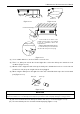
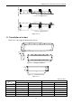
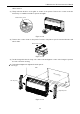
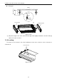
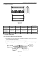
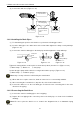
Table Of Contents
- 目录
- 第一部分 产品篇
- 第二部分 控制篇
- CONTROL
- 1 OPERATION FLOWCHART
- 2 WIRELESS REMOTE CONTROLLER
- 3 WIRED CONTROLLER
- 4 OPERATION INSTRUCTION OF SPECIAL FUNCTIONS
- 4.1 Setting of Filter Clean Reminder Function
- 4.2 Low Temperature Drying Function
- 4.3 Lock Function
- 4.4 Memory Function
- 4.5 Door Control Function/Human Sensitive Function
- 4.6 Switch between Fahrenheit and Centigrade
- 4.7 Enquiry of Ambient Temperature
- 4.8 Enquiry of Historical Malfunction
- 4.9 Debugging Function
- 4.9.1 Setting ambient temperature sensor (dual ambient temperature sensors function)
- 4.9.2 Selecting three speeds in high speed and three speeds in low speed of indoor fan motor
- 4.9.3 Displaying setting of freeze protection error code
- 4.9.4 Setting refrigerant lacking protection function
- 4.9.5 Selecting blowing residual heating of indoor unit
- 4.9.6 Mode selecting of compressor electric heating belt
- 4.9.7 Selecting low-power consumption mode
- 4.9.8 Selecting door control function
- 4.9.9 Selecting human sensitive function
- 4.9.10 Selecting long-distance monitoring or centralized controller
- 4.9.11 Selecting fan mode of indoor fan motor
- 4.9.12 Selecting compensation of temperature sensor at air return
- 5 INSTALLATION OF WIRED CONTROLLER
- 6 TROUBLESHOOTING
- 7 CENTRALIZED CONTROLLER
- 7.1 Smart Zone Controller
- 7.2 Additional Special Functions
- 7.2.1 Door control function
- 7.2.2 Human sensitive function
- 7.2.3 MODBUS interface
- 7.2.4 Connect to interface of centralized controller:
- 7.2.5 Light board control:
- 7.2.6 Malfunction output of relay:
- 7.2.7 Reserved fresh air valve interface for duct type unit
- 7.2.8 Interface of anion generator
- 7.2.9 Chassis electric heating belt of outdoor unit is optional
- CONTROL
- 第三部分 安装篇
- INSTALLATION
- 1 INDOOR UNIT INSTALLATION
- 1.1 Installation of Duct Type
- 1.2 Installation of Floor Ceiling Type
- 1.3 Installation of Cassette Type
- 1.3.1 Before Installation
- 1.3.2 Installation Site
- 1.3.3 Installing the Main Body Unit
- 1.3.4 Installing the Suspension Bolts
- 1.3.5 Leveling
- 1.3.6 The Panel Installation
- 1.3.7 Dimension Data
- 1.3.8 Installation of Drain Piping
- 1.3.9 Installing the Drain Pipes
- 1.3.10 Precautions When Doing Riser Piping Work
- 1.3.11 Testing of Drain Piping
- 2 OUTDOOR UNIT INSTALLATION
- 3 REFRIGERATION PIPING WORK
- 3.1 Refrigeration Piping Work Procedures and Caution in Connecting
- 3.2 Specification of Connection Pipe
- 4 ELECTRIC WIRING WORK
- 1 INDOOR UNIT INSTALLATION
- INSTALLATION
- 第四部分 维护篇(上)4.1~4.3
- 第四部分 维护篇(中)4.4拆装
- 第四部分 维护篇(下)4.5爆炸图及清单

U-Match Series DC Inverter Service Manual
59
Drain hose insulation
Drain port
Insulated drain hose
Insulated drain hose
Unit
0mm(0inch)
Drain hose insulation
Drain port
Drain cap
0mm(0inch)
Unit
Drain cap
Figure 3-1-13 Figure 3-1-14
(11) There is adhesive on one side of the insulation so that after removing the protective paper over it
the insulation can be directly attached to the drain hose.
(12) Considerations for the unit with the condensate pump:
1) For the unit with the condensate pump, only one drain port at the side close to the electric box
is prepared and only through it the drain hose can be connected.
2) See table 3 for the size of the drain port of the unit with the condensate pump, which is different
from that of the unit without the condensate pump.
3) For the unit with the condensate pump, two drain ports at the bottom are defaulted to be factory
plugged with drain caps. After the installation of the drain hose, these two drain ports also need
to be insulated properly with the same way aforementioned.
4) The drain hose for the unit with the condensate pump should be arranged as shown in the
figure below.
Ceiling
Hoisting stand
Clamp(attachment)
Drain hose(attachment)
Drain raising
hose
≤300mm(11-3/4inch)
1000~1500mm(39-3/8~59inch)
≤100mm
(39-3/8inch)
Figure 3-1-15
① The vertical height of the drain hose should be 75mm (3inch) or less so that it is unnecessary
for the drain port to withstand additional force.
Drain hose(attachment)
≤75mm(3inch)
≤1000mm
(39-3/8inch)
Figure 3-1-16
② When multiple drain hoses are used, their installation should be performed as shown in the
figure below.