
Service Manual
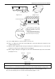
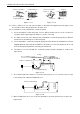
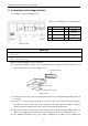
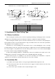
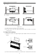
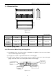
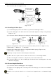
Table Of Contents
- 目录
- 第一部分 产品篇
- 第二部分 控制篇
- CONTROL
- 1 OPERATION FLOWCHART
- 2 WIRELESS REMOTE CONTROLLER
- 3 WIRED CONTROLLER
- 4 OPERATION INSTRUCTION OF SPECIAL FUNCTIONS
- 4.1 Setting of Filter Clean Reminder Function
- 4.2 Low Temperature Drying Function
- 4.3 Lock Function
- 4.4 Memory Function
- 4.5 Door Control Function/Human Sensitive Function
- 4.6 Switch between Fahrenheit and Centigrade
- 4.7 Enquiry of Ambient Temperature
- 4.8 Enquiry of Historical Malfunction
- 4.9 Debugging Function
- 4.9.1 Setting ambient temperature sensor (dual ambient temperature sensors function)
- 4.9.2 Selecting three speeds in high speed and three speeds in low speed of indoor fan motor
- 4.9.3 Displaying setting of freeze protection error code
- 4.9.4 Setting refrigerant lacking protection function
- 4.9.5 Selecting blowing residual heating of indoor unit
- 4.9.6 Mode selecting of compressor electric heating belt
- 4.9.7 Selecting low-power consumption mode
- 4.9.8 Selecting door control function
- 4.9.9 Selecting human sensitive function
- 4.9.10 Selecting long-distance monitoring or centralized controller
- 4.9.11 Selecting fan mode of indoor fan motor
- 4.9.12 Selecting compensation of temperature sensor at air return
- 5 INSTALLATION OF WIRED CONTROLLER
- 6 TROUBLESHOOTING
- 7 CENTRALIZED CONTROLLER
- 7.1 Smart Zone Controller
- 7.2 Additional Special Functions
- 7.2.1 Door control function
- 7.2.2 Human sensitive function
- 7.2.3 MODBUS interface
- 7.2.4 Connect to interface of centralized controller:
- 7.2.5 Light board control:
- 7.2.6 Malfunction output of relay:
- 7.2.7 Reserved fresh air valve interface for duct type unit
- 7.2.8 Interface of anion generator
- 7.2.9 Chassis electric heating belt of outdoor unit is optional
- CONTROL
- 第三部分 安装篇
- INSTALLATION
- 1 INDOOR UNIT INSTALLATION
- 1.1 Installation of Duct Type
- 1.2 Installation of Floor Ceiling Type
- 1.3 Installation of Cassette Type
- 1.3.1 Before Installation
- 1.3.2 Installation Site
- 1.3.3 Installing the Main Body Unit
- 1.3.4 Installing the Suspension Bolts
- 1.3.5 Leveling
- 1.3.6 The Panel Installation
- 1.3.7 Dimension Data
- 1.3.8 Installation of Drain Piping
- 1.3.9 Installing the Drain Pipes
- 1.3.10 Precautions When Doing Riser Piping Work
- 1.3.11 Testing of Drain Piping
- 2 OUTDOOR UNIT INSTALLATION
- 3 REFRIGERATION PIPING WORK
- 3.1 Refrigeration Piping Work Procedures and Caution in Connecting
- 3.2 Specification of Connection Pipe
- 4 ELECTRIC WIRING WORK
- 1 INDOOR UNIT INSTALLATION
- INSTALLATION
- 第四部分 维护篇(上)4.1~4.3
- 第四部分 维护篇(中)4.4拆装
- 第四部分 维护篇(下)4.5爆炸图及清单

U-Match Series DC Inverter Service Manual
62
maintenance etc., as shown in Figure 3-1-22.
Supply air
Return air
1
Supply air
Return air
Install the return air duct(a) Install the return air duct(b)
2
4
5
5
4
6
3
1
Figure 3-1-22
Table 3-1-5 Installation of the return air duct
No.
Name
No.
Name
1
Return Air Inlet (with filter)
4
Indoor unit
2
Canvas Duct
5
Supply Air Duct
3
Return Air Duct
6
Grille
1.2 Installation of Floor Ceiling Type
1.2.1 Before Installation
After receiving the machine, please check for any transport damage. If finding any surface or internal
damage, please immediately report to the transport company or equipment company in writing.
After receiving the machine, please check the unit and accessories in reference to the packing list.
Ensure that the model is correct and the machine is in good condition. Please also check if the specification
and quantity of accessory parts are correct.
Determine the correct handling route and methods, thus to avoid damaging the unit or causing
possible hazard. For the sake of protection and safety, it is suggested to move the unit with the packaging
box. Even though it is not permitted to do like this under special occasions, do not remove the packaging
box, thus to avoid loosening or falling during handling.
Confirm if the installing foundation is solid. When this unit is to be installed on the metal section of the
building, make sure that the electrical insulation must comply with applicable standards.
Ensure that the place of installation is far from the area where the inflammable or explosive
substances are stored, thus to avoid possible explosion or fire due to leakage.
1.2.2 Installation Site
(1) Install the unit at a place where is strong enough to withstand the weight of the unit.
(2) The air inlet and outlet of the unit should never be clogged so that the airflow can reach every
corner of the room.
(3) Leave service space around the unit as required in Figure 3-1-23.