
Service Manual

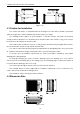
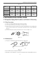
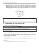
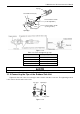
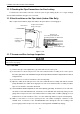
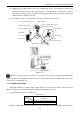
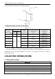
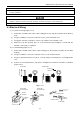
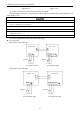
Table Of Contents
- 目录
- 第一部分 产品篇
- 第二部分 控制篇
- CONTROL
- 1 OPERATION FLOWCHART
- 2 WIRELESS REMOTE CONTROLLER
- 3 WIRED CONTROLLER
- 4 OPERATION INSTRUCTION OF SPECIAL FUNCTIONS
- 4.1 Setting of Filter Clean Reminder Function
- 4.2 Low Temperature Drying Function
- 4.3 Lock Function
- 4.4 Memory Function
- 4.5 Door Control Function/Human Sensitive Function
- 4.6 Switch between Fahrenheit and Centigrade
- 4.7 Enquiry of Ambient Temperature
- 4.8 Enquiry of Historical Malfunction
- 4.9 Debugging Function
- 4.9.1 Setting ambient temperature sensor (dual ambient temperature sensors function)
- 4.9.2 Selecting three speeds in high speed and three speeds in low speed of indoor fan motor
- 4.9.3 Displaying setting of freeze protection error code
- 4.9.4 Setting refrigerant lacking protection function
- 4.9.5 Selecting blowing residual heating of indoor unit
- 4.9.6 Mode selecting of compressor electric heating belt
- 4.9.7 Selecting low-power consumption mode
- 4.9.8 Selecting door control function
- 4.9.9 Selecting human sensitive function
- 4.9.10 Selecting long-distance monitoring or centralized controller
- 4.9.11 Selecting fan mode of indoor fan motor
- 4.9.12 Selecting compensation of temperature sensor at air return
- 5 INSTALLATION OF WIRED CONTROLLER
- 6 TROUBLESHOOTING
- 7 CENTRALIZED CONTROLLER
- 7.1 Smart Zone Controller
- 7.2 Additional Special Functions
- 7.2.1 Door control function
- 7.2.2 Human sensitive function
- 7.2.3 MODBUS interface
- 7.2.4 Connect to interface of centralized controller:
- 7.2.5 Light board control:
- 7.2.6 Malfunction output of relay:
- 7.2.7 Reserved fresh air valve interface for duct type unit
- 7.2.8 Interface of anion generator
- 7.2.9 Chassis electric heating belt of outdoor unit is optional
- CONTROL
- 第三部分 安装篇
- INSTALLATION
- 1 INDOOR UNIT INSTALLATION
- 1.1 Installation of Duct Type
- 1.2 Installation of Floor Ceiling Type
- 1.3 Installation of Cassette Type
- 1.3.1 Before Installation
- 1.3.2 Installation Site
- 1.3.3 Installing the Main Body Unit
- 1.3.4 Installing the Suspension Bolts
- 1.3.5 Leveling
- 1.3.6 The Panel Installation
- 1.3.7 Dimension Data
- 1.3.8 Installation of Drain Piping
- 1.3.9 Installing the Drain Pipes
- 1.3.10 Precautions When Doing Riser Piping Work
- 1.3.11 Testing of Drain Piping
- 2 OUTDOOR UNIT INSTALLATION
- 3 REFRIGERATION PIPING WORK
- 3.1 Refrigeration Piping Work Procedures and Caution in Connecting
- 3.2 Specification of Connection Pipe
- 4 ELECTRIC WIRING WORK
- 1 INDOOR UNIT INSTALLATION
- INSTALLATION
- 第四部分 维护篇(上)4.1~4.3
- 第四部分 维护篇(中)4.4拆装
- 第四部分 维护篇(下)4.5爆炸图及清单

U-Match Series DC Inverter Service Manual
79
>500mm
(1-2/3feet)
>2000mm
(6-5/9feet)
>500mm
(1-2/3feet)
>500mm
(1-2/3feet)
>500mm
(1-2/3feet)
>2000mm
(6-5/9feet)
>1000mm
(3-2/7feet)
Figure 3-2-1
2.3 Caution for Installation
The outdoor unit shall be so installed that the air discharged out of the outdoor unit will not flow back
and that enough space shall be maintained around the machine for repair;
The installing position shall be in good ventilation, so that the machine can breathe and exhaust
enough air. Ensure that there is no obstruction at the inlet and outlet of the machine. If any, please remove
the obstructions blocking the air inlet and outlet.
If the outdoor unit is installed on concrete or solid ground, it shall be fixed by using M10 bolts and nuts.
And ensure that the machine is kept vertical and horizontal.
The outdoor unit must be lifted by using the designated lift hole. During lifting, take care to protect the
air conditioner and avoid knocking the metal parts, thus to prevent rusting in the future.
To meet the noise and vibration requirements, the outdoor unit shall be installed by using rubber
damping pad or spring damper.
To install the drainage pipe, please insert the drainage joint to the drainage hole on the outdoor
chassis and connect a drainage pipe on the drainage joint. (The installing height of outdoor unit shall be at
least 5cm (2inch) if drainage joint is to be used).
To insert the pipe through the wall, the wall-cross tube must be installed.
The installing dimension shall comply with the installation requirements in these instructions. The
outdoor unit must be fixed at the installing position.
The installation shall be done by specialist technicians.
2.4 Dimension Data
D
A
B
C
E
Figure 3-2-2